


Connector pin assignments 557
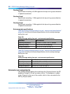
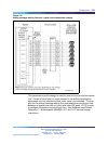
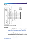
Telephone lines from station equipment cross connect to the analog
message waiting line card at the MDF using a wiring plan similar to
that used for trunk cards. A typical connection example is shown in
Figure 137 "Analog message waiting line card - typical cross connection
example" (page 559) and Table 132 "CLASS modem card - environmental
specifications" (page 323) shows the I/O pin designations at the backplane
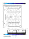
connector. This connector is arranged as an 80-row by 2-column array of
pins. Normally, these pin positions are cabled to 50-pin connectors at the
I/O panel in the rear of each module for connection with 25-pair cables to
the cross-connect terminal.
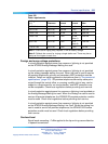
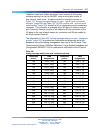
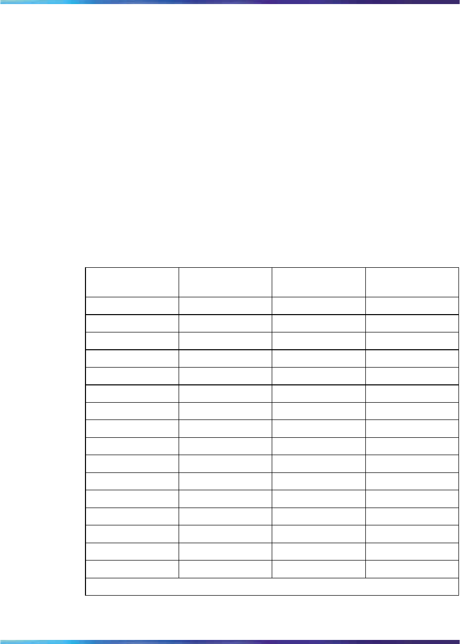
The information in Table 225 "Analog message waiting line card - backplane
pinouts" (page 557) is provided as a reference and diagnostic aid at the
backplane, since the cabling arrangement may vary at the I/O panel. See
Communication Server 1000M and Meridian 1 Large System Installation and
Configuration (NN43021-310) for cable pinout information at the I/O panel.
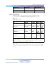
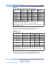
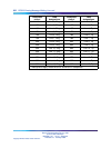
Table 225
Analog message waiting line card - backplane pinouts
Backplane
pinout*
Lead
designations
Backplane
pinout*
Lead
designations
12A Line 0, Ring 12B Line 0, Tip
13A Line 1, Ring 13B Line 1, Tip
14A Line 2, Ring 14B Line 2, Tip
15A Line 3, Ring 15B Line 3, Tip
16A Line 4, Ring 16B Line 4, Tip
17A Line 5, Ring 17B Line 5, Tip
18A Line 6, Ring 18B Line 6, Tip
19A Line 7, Ring 18B Line 7, Tip
62A Line 8, Ring 62B Line 8, Tip
63A Line 9, Ring 63B Line 9, Tip
64A Line 10, Ring 64B Line 10, Tip
65A Line 11, Ring 65B Line 11, Tip
66A Line 12, Ring 66B Line 12, Tip
67A Line 13, Ring 67B Line 13, Tip
68A Line 14, Ring 68B Line 14, Tip
69A Line 15, Ring 69B Line 15, Tip
* These pinouts apply to both NT8D37 and NT8D11 backplanes.
Nortel Communication Server 1000
Circuit Card Reference
NN43001-311 01.04 Standard
Release 5.0 23 May 2008
Copyright © 2003-2008, Nortel Networks
.