


Configuration 787
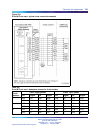
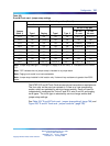
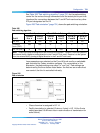
Table 303
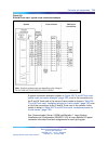
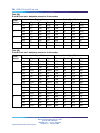
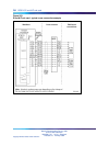
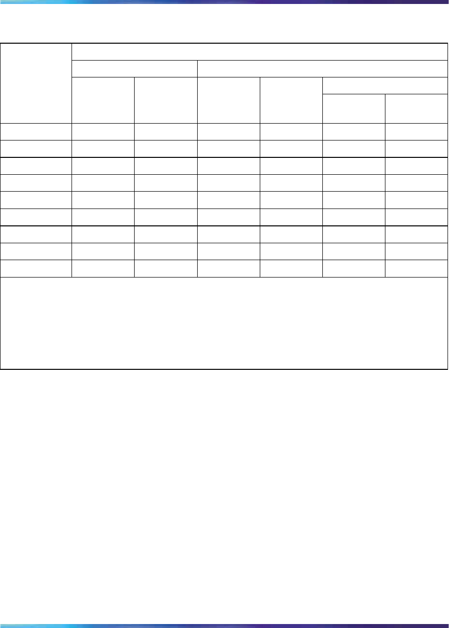
E and M Trunk card - jumper strap settings
Mode of operation (Note 2)
2-wire trunk 4-wire trunk
DX tip & ring pair
Jumper
(Note 1) Type I Paging Type I Type II
M—rcv
E—xmt
E—rcv
M—xmt
J1.X Off Off Off Off Pins 1–2 Pins 2–3
J2.X On On (Note 3) On On Off Off
J3.X Off Off Off Off (Note 4) (Note 4)
J4.X Off Off Off Off Pins 2–3 Pins 1–2
J5.X Off Off Off Off (Note 4) (Note 4)
J6.X Off Off Off Off On On
J7.X Off Off Off Off On On
J8.X Off Off Off Off On On
J9.X Pins 2–3 Pins 2–3 Pins 2–3 Pins 2–3 Pins 1–2 Pins 1–2
Note: Jumper strap settings J1.X through J9.X apply to all four units; "X" indicates the unit number,
0–3.
Note: "Off" indicates that no jumper strap is installed on a jumper block.
Note: Paging trunk mode is not zone selectable.
Note: Jumper strap installed in this location only if external loop resistance is greater than 2500
ohms.
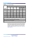
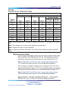
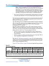
The NT8D15 E and M Trunk Card serves various transmission requirements.
The four units on the card can operate in A-Law or µ-Law companding
modes, which are selected by service change entries. Each unit can be
independently configured for 2-wire E and M, 4-wire E and M, and paging
trunk types. The trunk type is selected by service change entries and
jumper strap settings.
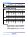
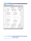
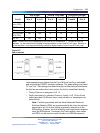
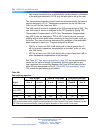
See Table 304 "E and M Trunk card - jumper strap settings" (page 788) and
Figure 255 "E and M Trunk card - jumper locations" (page 786).
Nortel Communication Server 1000
Circuit Card Reference
NN43001-311 01.04 Standard
Release 5.0 23 May 2008
Copyright © 2003-2008, Nortel Networks
.