


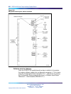
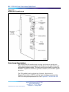

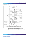
816 NT8D41AA Serial Data Interface Paddle Board
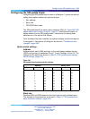
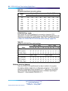
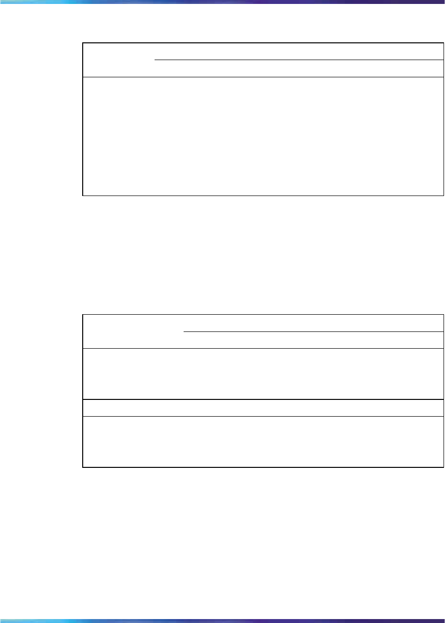
Table 317
SDI paddle board baud rate switch settings
Port 1 – SW2 Port 2 – SW3
Baud
rate
12341234
150
off off
on on
off off
on on
300
off
on
off
on
off
on
off
on
600
off off off
on
off off off
on
1200
off
on on
off off
on on
off
2400
off off
on
off off off
on
off
4800
off
on
off off off
on
off off
9600
off off off off off off off off
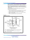
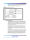
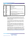
DTE/DCE/Fiber mode
Each serial port can be configured to connect to a terminal (DTE
equipment), a modem (DCE equipment), or a Fiber Superloop Network card.
Instructions for setting the switches SW5, SW6, SW7, and SW8 are shown
in Table 318 "NT8D41AA DTE/DCE/Fiber switch settings" (page 816).
Table 318
NT8D41AA DTE/DCE/Fiber switch settings
Port 1 – SW5 Port 1 – SW6
Mode 1 2 3 4
5
61234
5
6
DTE (terminal)
on on on on on on
off off off off off off
DCE (modem) off off off off off off
on on on on on on
NT1P61 (Fiber)
on on on on on
off off off
on on on on
Port 2 – SW7 Port 2 – SW8
DTE (terminal)
on on on on on on
off off off off off off
DCE (modem) off off off off off off
on on on on on on
NT1P61 (Fiber)
on on on on
off off off off
on on on on
Software service changes
Once the NT8D41 SDI paddle board has been installed in the system,
the system software needs to be configured to recognize it. This is done
using the Configuration Record program LD 17. Instructions for running
the Configuration Record program are found in Software Input/Output
Reference — Administration (NN43001-611).
Nortel Communication Server 1000
Circuit Card Reference
NN43001-311 01.04 Standard
Release 5.0 23 May 2008
Copyright © 2003-2008, Nortel Networks
.