


Connector pin assignments 1107
Connector pin assignments
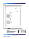
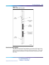
Connector J1 is connected to port one, and uses the RS-232-C standard
DB-25-pinout. Connector J2 is connected to ports two, three, and four, and
is a non-standard pinout that requires an adapter cable. An adapter cable
(NT8D96) splits the J2 signals out to three standard RS-232-C connectors.
Port 2 is connected to connector A, Port 3 is connected to connector B, and
Port 4 is connected to connector C.
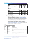
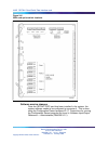
Table 451 "Connector J1 pin assignments" (page 1107) shows the pinouts
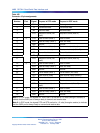
for connector J1, and Table 452 "Connector J2 pin assignments" (page
1108) shows the pinouts for connector J2.
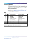
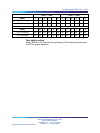
Table 451
Connector J1 pin assignments
Pin
number Signal Purpose in DTE mode Purpose in DCE mode
1
FGD Frame ground Frame ground
2
TD Received data Transmitted data
3
RD Transmitted data Received data
4
RTS Request to send (not used) Request to send (Note 2)
5
CTS Clear to send (Note 1) Clear to send
6
DSR Data set ready (Note 1) Data set ready
7
GND Ground Ground
8
CD Carrier detect (Note 1) Carrier detect (not used)
20
DTR Data terminal ready Data terminal ready (Note 2)
Note 1: In DTE mode, the signals CD, DSR, and CTS are tied to +12 volts (through a resistor) to
indicate that the QSDI port is always ready to transmit and receive data.
Note 2: In DCE mode, the signals DTR, and RTS are tied to +12 volts (through a resistor) to
indicate that the QSDI port is always ready to transmit and receive data.
Nortel Communication Server 1000
Circuit Card Reference
NN43001-311 01.04 Standard
Release 5.0 23 May 2008
Copyright © 2003-2008, Nortel Networks
.