


Physical description 329
•
After power-up, before the card is enabled.
•
When the ENET port on the card is disabled by software.
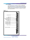
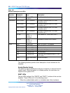
Trunk Disable (DIS) LEDs
Two red LEDs indicate if the "trunk port 0" or "trunk port 1" portions of the
card are disabled. These LEDs are lit in the following cases:
•
Upon reception of the "disable loop" message from the software.
•
After power-up.
OOS LEDs
Two yellow LEDs indicate if the "trunk port 0" and "trunk port 1" portions of
the card are out of service.
NEA LEDs
Two yellow LEDs indicate if the near end detects absence of incoming signal
or loss of synchronization in "trunk port 0" or "trunk port 1" respectively.
The near-end alarm causes a far-end alarm signal to be transmitted to
the far end.
FEA LEDs
Two yellow LEDs indicate if a far-end alarm has been reported by the far
end (usually in response to a near-end alarm condition at the far end) on
"trunk port 0" or "trunk port 1".
LBK LEDs
Two yellow LEDs indicate if a remote loopback test is being performed on
trunk port 0 or trunk port 1. The loopback indication is active when the
digital trunk is in remote loopback mode. Normal call processing is inhibited
during the remote loopback test.
DCH LED
When the dual colored LED is red, it indicates the on-board DDCH is
present but disabled. When the dual colored LED is green, it indicates the
on-board DDCH is present and enabled. If a DDCH is not configured on
the DDP2 card, this lamp is not lit.
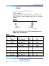
Unit 0 Clk Connectors
Two RJ11 connectors for connecting:
•
Digital trunk unit 0 recovered clock to pr imary or secondary reference
source on clock controller card 0.
•
Digital trunk unit 0 recovered clock to pr imary or secondary reference
source on clock controller card 1.
Nortel Communication Server 1000
Circuit Card Reference
NN43001-311 01.04 Standard
Release 5.0 23 May 2008
Copyright © 2003-2008, Nortel Networks
.