


Physical description 881
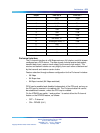
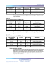
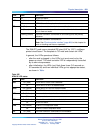
LED
State
Definition
Off No far end alarm.
LBK
On (Yellow) NTAK10 is in loop-back mode.
Off NTAK10 is not in loop-back mode.
CC
On (Red) The clock controller is switched on and disabled.
On (Green) The clock controller is switched on and is either locked to a reference
or is in free-run mode.
Flashing (Green) The clock controller is switched on and locking onto the primary
reference.
Off The clock controller is switched off.
Note: See "Clock controller interface" (page 894) in this chapter for
more on tracking and free-run operation.
The 2Mb DTI pack uses a standard IPE-sized (9.5" by 12.5"), multilayer
printed circuit board. The faceplate is 7/8" wide and contain six LEDs.
In general, the LEDs operate as follows:
•
after the card is plugged in, the LEDs (a-e) are turned on by the
power-up circuit. The clock controller LED is independently controlled
by its own microprocessor
•
after initialization, the LEDs (a-e) flash three times (0.5 seconds on,
0.5 seconds off) and then individual LEDs go into appropriate states,
as shown in Table.
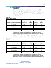
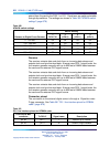
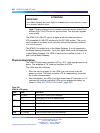
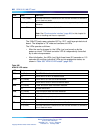
Table 365
NTAK10 LED states
LED
State
Definition
DIS
On (Red) The NTAK10 circuit card is disabled.
Off The NTAK10 is not in a disabled state.
OOS
On (Yellow) The NTAK10 is in an out of service state
Off The NTAK10 is not in an out of service state
NEA
On (Yellow) A near end alarm state has been detected
Off No near end alarm
FEA
On (Yellow) A far end alarm state has been detected
Off No far end alarm
LBK
On (Yellow) NTAK10 is in loop-back mode
Off NTAK10 is not in loop-back mode
CC
On (Red) The clock controller is switched on and disabled
Nortel Communication Server 1000
Circuit Card Reference
NN43001-311 01.04 Standard
Release 5.0 23 May 2008
Copyright © 2003-2008, Nortel Networks
.