


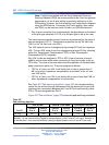

Configuration 791
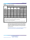
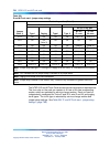
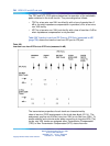
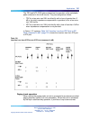
See Table 306 "Pad switching algorithm" (page 791) for the pad switching
control for the various through connections and the actual port-to-port loss
introduced for connections between the E and M Trunk card and any other
IPE port designated as Port B.
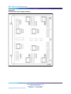
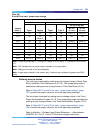
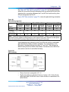
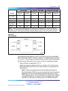
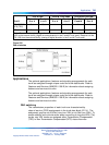
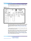
Figure 256 "Pad orientation" (page 791) shows the pad switching orientation.
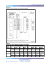
Table 306
Pad switching algorithm
Port B pads E and M Trunk Pads Port-to-port loss (dB)
Port B
Transmit
DtoA
Receive
AtoD
Transmit
DtoA
Receive
AtoD
Port B to
E and M
E and M to
Port B
IPE line N/A N/A Out In
2.5 3.5
Universal
trunk (TRC)
Out Out In In
00
IPE TIE (VNL) In Out In Out
00
Note: Transmit and receive designations are from and to the system. Transmit is from the system to
the external facility (digital-to-analog direction in the E and M Trunk card). Receive is to the system
from the external facility (analog-to-digital direction in the E and M Trunk card).
Loss parameters are selected on the E and M trunk card by a switchable
pad controlled by Codec emulation software. For convenience in this
discussion, the pads settings are called "in" and "out." Pad settings are
determined by the three factors listed below: the first two are under direct
user control; the third is controlled indirectly.
Figure 256
Pad orientation
•
Class of service is assigned in LD 14.
•
Facility termination is selected (2-wire or 4-wire) in LD 14 (the 2-wire
setting provides 0.5 dB more loss in each direction of transmission for
echo control).
Nortel Communication Server 1000
Circuit Card Reference
NN43001-311 01.04 Standard
Release 5.0 23 May 2008
Copyright © 2003-2008, Nortel Networks
.