


Functional description 547
•
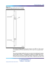
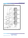
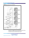
signaling and control circuits on the analog message waiting line card
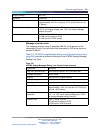
Microcontroller
The analog message waiting line card contains a microcontroller that
controls the internal operation of the card and the serial card LAN link to the
controller card. The microcontroller controls the following:
•
reporting to the CE CP through the card LAN link:
— card identification (card type, vintage, and serial number)
— firmware version
— self-test status
— programmed configuration status
•
receipt and implementation of card configuration:
— programming of the codecs
— enabling/disabling of individual units or entire card
— programming of input/output interface control circuits for
administration of line interface unit operation
— enabling/disabling of an interrupted dial tone to indicate call waiting
— maintenance diagnostics
— transmission loss levels
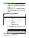
Signaling and control
The signaling and control portion of the card provides circuits that establish,
supervise, and take down call connections. These circuits work with the
system CP to operate the line interface circuits during calls. The circuits
receive outgoing call signaling messages from the CP and return incoming
call status information over the DS-30X network loop.
Circuit power
The +8.5 V dc input is regulated down to +5 V dc for use by the digital logic
circuits. All other power to the card is used by the line interface circuits. The
+15.0 V dc input is regulated down to +12 V dc to power the analog circuits.
The –48.0 V dc input is for the telephone battery.
Ringing power for telephones is 86 Vrms ac at 20 Hz on –48 V dc. The
Rsync signal is used to switch 20 Hz ringing on and off at the zero current
cross-over point to lengthen the life of the switching circuits.
Nortel Communication Server 1000
Circuit Card Reference
NN43001-311 01.04 Standard
Release 5.0 23 May 2008
Copyright © 2003-2008, Nortel Networks
.