


398 NT6D80 MSDL card
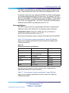
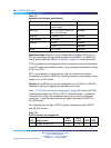
Table 171
Asynchronous interface specifications
Parameter
Specification Configured
Data bit, parity 7 bits even, odd or no parity, or
8 bits no parity
Software
Data rate 0.3, 0.6, (1.2), 2.4, 4.8, 9.6,
19.2, and 38.4 kbps
Software
Stop bits 1 (default), 1.5, 2 Software
Transmission Full Duplex N/A
Interface RS-232 Software
RS-422 Switches
Mode DTE or DCE Switches
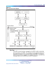
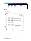
Emulation mode Each port can be configured to emulate a DCE port or a
DTE port by setting the appropriate switches on the MSDL. For details on
how to set the switches, refer to "Installation" (page 401) of this document.
DCE is a master or controlling device that is usually the source of information
to the DTE and may provide the clock in a synchronous transmission linking
a DCE to a DTE.
DTE is a peripheral or terminal device that can transmit and receive
information to and from a DCE and normally provides a user interface to the
system or to a DCE device.
Interface Each MSDL port can be configured as an RS-232 or an RS-422
interface by setting the appropriate switches on the card.
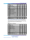
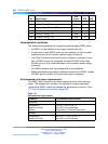
Table 172 "RS-232 interface pin assignments" (page 398) lists the RS-232
interface specifications for EIA and CCITT standard circuits. It shows the
connector pin number, the associated signal name, and the supported
circuit type. It also indicates whether the signal originates at the DTE or
the DCE device.
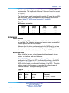
This interface uses a 26-pin (SCSI II) female connector for both RS-232
and RS-422 circuits.
Table 172
RS-232 interface pin assignments
Pin Signal name
EIA
circuit
CCITT
circuit DTE DCE
1
Frame Ground (FG) AA
102
——
Nortel Communication Server 1000
Circuit Card Reference
NN43001-311 01.04 Standard
Release 5.0 23 May 2008
Copyright © 2003-2008, Nortel Networks
.