


Line cards 21
Once these steps are complete, the terminal equipment is ready for use.
Operation
This section describes how line cards fit into the CS 1000E, CS 1000M, and
Meridian 1 architecture, the busses that carry signals to and from the line
cards, and how they connect to terminal equipment. These differences are
summarized in Table 2 "IPE module architecture" (page 21).
Host interface bus
Cards based on the IPE bus use a built-in microcontroller. The IPE
microcontroller is used to do the following:
•
perform local diagnostics (self-test)
• configure the card according to instructions issued by the system
•
report back to the system information such as card identification
(type, vintage, and serial number), firmware version, and programmed
configuration status)
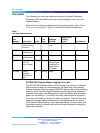
Table 2
IPE module architecture
Parameter IPE
Card Dimensions 31.75 x 25.4 x 2.2 cm (12.5 x10.0 x 0.875
in.).
Network Interface DS-30X Loops
Communication Interface card LAN Link
Microcontroller 8031/8051 Family
Peripheral Interface card NT8D01 Controller card
Network Interface card NT8D04 Superloop Network card
Modules NT8D37 IPE module
Intelligent Peripheral Equipment
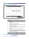
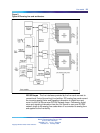
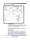
IPE line cards all share a similar architecture. Figure 2 "Typical IPE analog
line card architecture" (page 23) shows a typical IPE line card architecture.
The various line cards differ only in the number and types of line interface
units.
The switch communicates with IPE modules over two separate interfaces.
Voice and signaling data are sent and received over DS-30X loops, and
maintenance data is sent over a separate asynchronous communication
link called the card LAN link.
Signaling data is information directly related to the operation of the
telephone line. Some examples of signaling commands include:
•
off-hook/on-hook
Nortel Communication Server 1000
Circuit Card Reference
NN43001-311 01.04 Standard
Release 5.0 23 May 2008
Copyright © 2003-2008, Nortel Networks
.