


Operation 361
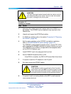
CAUTION
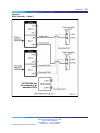
Clock Controller cables connecting the Clock Controller
and DDP2 card must NOT be routed through the center of
the cabinet past the power harness. Instead, they should
be routed around the outside of the equipment shelves.
7
Remove the DDP2 card only if both loops are disabled. If the other
circuit of a DDP2 card is in use, DO NOT remove the card. The
faceplate switch ENB/DIS must be in the OFF (DIS) position before
the card is removed, otherwise the system initializes.
8 Pack and store the NT5D97 card and circuit card.
—End—
Configuring the NT5D97
After the NT5D97 DDP2 is installed, configure the system using the same
procedures as the standard NT8D72BA PRI2.
Consider the following when configuring the NT5D97 DDP2 card:
•
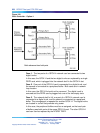
The CS 1000 software allows four ports to be defined for the NT6D80
MSDL. The DDCH (NTBK51AA) card has only two ports, 0 and 1;
therefore, ports 2 and 3 must not be defined when using the NTBK51AA.
•
Port 0 of the NTBK51AA can only be defined to work with Loop 0 of the
NT5D97 DDP2 card, and Port 1 of the NTBK51AA can only be defined
to work with Loop 1 of the NT5D97. This relationship must be reflected
when configuring a new DCH in LD 17 (in response to the DCHL prompt,
enter either 0 or 1 when specifying the loop number used by the DCH).
•
You cannot define one of the DDP2 loops for the NTBK51AA DDCH,
and the other loop for the NT6D11AF/NT5K75AA/NT5K35AA DCH card
or the NT6D80 MSDL.
•
When configuring the NT5D97 DDP2 in DTI2 outgoing dial pulse mode,
a Digit Outpulsing patch is required.
Testability and diagnostics
The DDP2 card supports testing and maintenance functions through the
following procedures:
•
Selftest upon power up or reset
• Signalling test performed in the LD 30
•
Loopback tests, self tests, and continuity tests performed by LD 60
and LD 45
Nortel Communication Server 1000
Circuit Card Reference
NN43001-311 01.04 Standard
Release 5.0 23 May 2008
Copyright © 2003-2008, Nortel Networks
.