


PNNI in an ATM Network
893-01006-C
4-3
other using logical links. On a logical (not physically attached) link, hello sending
is done by way of a routing control channel (RCC) based on a switched virtual
channel (SVC) connection. PNNI has been designed specifically for use in routing
SVCs across an ATM network.
Within each peer group, one switch, such as a Centillion 1000 switch, will be
elected peer group leader. Neighbors that are in different peer groups will not
exchange topology information and are “border nodes.” However, PNNI switches
may also be configured as a single PNNI group with no hierarchy, where it is not
necessary to elect a group leader.
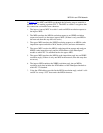
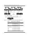
One use of PNNI is in the ATM LAN backbone. Typical configurations connect
frame-based desktop systems to an ATM edge switch, which connects to the ATM
backbone through a core switch. ATM servers and routers can connect directly to
the ATM backbone through the core switch or the edge switch. A big advantage of
ATM backbones over frame-based backbones is topology knowledge. ATM nodes
supporting PNNI understand the ATM topology and provide traffic flow
protection against link failures by establishing load balancing across redundant
ATM links. In contrast, UNI connections with edge switches do not participate in
network topology.
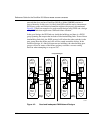
As with IISP, PNNI provides network loop protection and redundant links as
described in Chapter 5, “
IISP in an ATM Network,” in the sections on “How a
Link Group Provides Loop Prevention” on page 5-7 and “Example of IISP and
Redundant Links in a Network” on page 5-11. The difference is that these
functions are done automatically with PNNI.
Using PNNI with the Centillion 50/100 or Model 5000BH
Switches
The advanced image for the Centillion 50/100 and Model 5000BH switches
supports PNNI. You can use SpeedView to configure PNNI within each switch.
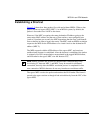
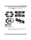
The hierarchical network design shown in Figure 4-1
is an example of a PNNI
network using Centillion 50/100 or Model 5000BH switches. This network
includes two core switches and a number of transit switches and allows for a
PNNI hierarchy of switches with each transit switch pair and its associated edges
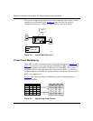
forming the lowest-level PNNI group. Table 4-1
shows a possible addressing
scheme for this network.