


PNNI in an ATM Network
893-01006-C
4-13
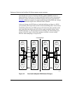
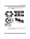
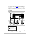
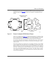
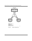
Problems can occur when mixing PNNI and IISP in networks if the design is not
carefully thought out. Figure 4-5 contains two examples of inadequate network
design.
Figure 4-5. Example of Inadequate IISP/PNNI Network Designs
The No Core design in the Figure 4-5 is particularly dangerous in situations where
there are more than three PNNI groups that are not interconnected in a full mesh
because IISP link states will not propagate correctly between PNNI groups.
For example, if the link between groups 1 and 6 fails, then groups 5 and 2 will not
be aware of this and may try to connect to each other by way of groups 1 and 6,
which will fail.
The Links Avoiding Core example shows two problems. The first concerns PNNI
group 3, which is not connected to the core at all. PNNI group 3 has no idea of the
status of the links to the core from groups 4 and 2 (L4C and L2C). For example, if
L4C fails, a switch in group 3 may still attempt to route a call to the core through
L34A. The call will then probably return to group 3 via L34B, creating a routing
loop. If both L4C and L2C fail, all calls between any of the three groups and the
core will loop continuously.
8331EA
Inadequate IISP Linking
Between Groups
PNNI
group 1
PNNI
group 2
PNNI
group 5
PNNI
group 4
L16
L6C
L15
L3C
L56
L4C
L5C
Links
Avoiding Core
No Core
IISP
links
L4C
L23A
L4C
L34B
L34A
PNNI
group 6
PNNI
group 3
PNNI
core
PNNI
group 1
PNNI
group 2
PNNI
group 5
PNNI
group 4
PNNI
group 6
PNNI
group 3