


IISP in an ATM Network
893-01006-C
5-7
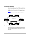
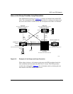
How a Link Group Provides Loop Prevention
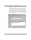
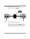
The ATM network topology in Figure 5-3 consists of alternate and parallel IISP
links. The assumption for this scenario is that client A is setting up a connection to
the server and switch 3 is down before the call request from client A is initiated.
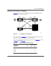
Figure 5-3. Example of Link Groups and Loop Prevention
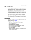
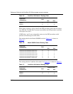
When client A places a call request to the server, the IISP procedure checks for
link availability and determines that IISP link 2 is down. The IISP procedure
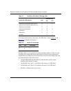
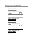
searches the routing table (Table 5-1
) for an alternate route by selecting the next
best match to the ATM address of the server.
644EA
Centillion 100 switch 1
Remote Centillion 100
switch
ATM prefix
39.00.00.00.00.00.00.05.00.00.00.07.01
ATM prefix
39.00.00.00.00.00.00.05.00.00.00.07.03
Model 5000BH switch
ATM prefix
39.00.00.00.00.00.00.06.00.00.00.03.02
ATM prefix
39.00.00.00.00.00.00.01.00.00.00.01.00
Centillion 100 switch 3
ATM prefix
39.00.00.00.00.00.00.05.00.00.00.07.02
Centillion 100
switch 2
Private
UNI
Client A
Server
IISP link 5
IISP link 6
Link
group 1
S2/P1
IISP
link 1
IISP
link 3
IISP
link 2
IISP
link 4
S2/P2
S1/P2
S1/P1
S1/P2
Switch
down
S3/P1
S5/P3
S5/P1
S5/P2
S3/P2
S1/P1
S1/P1
S1/P2