


Page: 99
Service Guide ML590/ML591
Chapter 3 Maintenance & Disassembly
3.2.07 Control Board (AKGI)
1. Perform these procedures:
3.2.01
3.2.06
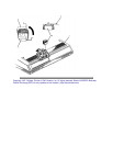
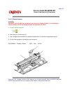
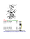
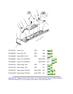
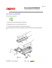
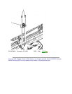
2. Remove the two screws (1).
3. Release the control board (AKGI) (2) from the bracket (3).
4. Tilt the board to access the connectors.
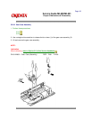
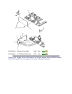
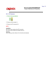
5. Detach connectors CN7 - operator panel (4), CN8 - carriage cable (5), CN3 - power supply (6),
and CN6 - line feed motor (7).
6. Remove the board.
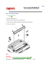
NOTE:
Installation:
The bottom sensor lever must be positioned in the SNS3 sensor (8).
The rear sensor lever must be positioned in the SNS1 sensor (9).
The cut sheet/continuous sensor lever must be positioned below the BASW sensor (10). The
lever should contact the sensor only when the change lever is in the top feed (middle) setting.
The IC: EEPROM is soldered in on the board.