


Page: 67
Service Guide ML590/ML591
Chapter 2 Principles of Operation
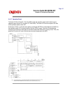
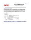
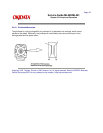
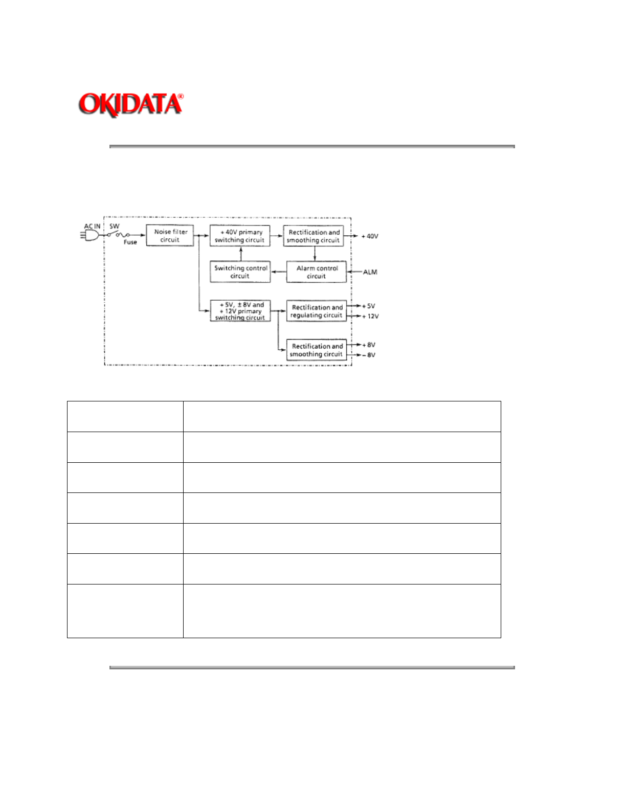
2.1.09 Power Supply Circuit
The switching type power supply circuit supplies the +5 vdc, +/-8 vdc, +12 vdc and +40 vdc.
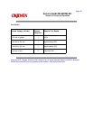
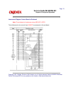
Table of Output Voltages
Voltage / Signal
Purpose
+5 vdc IC logic levels LED drive voltages
+8 vdc Serial interface line voltage comparator IC
-8 vdc Serial interface line voltage
+12 vdc Printhead analog circuit
+40 vdc Printhead space motor and line feed motor drive voltage
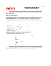
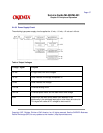
ALM Output from the main control board upon detection of an
abnormality in the printhead head gap or color ribbon drive circuits.
This signal will cause all DC voltages to be turned off.
Copyright 1997, Okidata, Division of OKI America, Inc. All rights reserved. See the OKIDATA Business
Partner Exchange (BPX) for any updates to this material. (http://bpx.okidata.com)