


Page: 186
Service Guide ML590/ML591
Chapter A Reference Charts
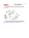
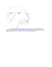
A.2.03 Power Supply Assembly
Firmware
NONE
Fuses
F1: 125/250V 5 amp. (AC LINE Fuse)
F2: 125/250V 2.5 amp. (Protects +5 vdc circuit)
Jumpers
NONE
Sensors
NONE
Switches
SW: Power Switch
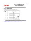
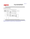
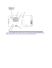
Test Points
+5 vdc: (Logic, LED Drive Voltage) CN2 - Pins 5 and 6
- 8 vdc: (Serial Interface Line Voltage) CN2 - Pin 11
+8 vdc: (Serial Interface Line Voltage, Comparator Voltage) CN2 - Pin 10
+12 vdc: (Printhead Analog Voltage)CN2 - Pin 9
+40 vdc: (Printhead, Space Motor / Line Feed Motor Drive Voltage)CN2 - Pins 1 and 2
Frame Ground: CN2 - Pins 3 and 4
Logic Ground: CN2 - Pins 7 and 8
ALM: (Alarm Signal from Main Control Board) CN2 - Pin 12