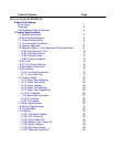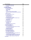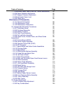
Table of Contents Page
....1.10.08 OKISmart Typer Utility 41
....1.10.09 OKISmart Panel Utility 42
1.11 Reliability 43
2 Principles of Operation
2.1 Electrical Operation 44
....2.1.02 Main Control Board 45
........Block Diagram 46
........Program ROM 47
........RAM 48
........Character Generator ROM (CG ROM) 49
........Electrically Erasable Programmable ROM (EEPROM) 50
........LSI 51
....2.1.03 Initialization 52
....2.1.04 Parallel Interface Control 53
....2.1.05 Print Control 54
........LSI/Printhead Interface 55
........Gap Adjust Control 56
........Print Compensation Control 57
....2.1.06 Space and Line Feed (SP/LF) Motor Control 58
........Line Feed Motor Control 59
........Space Motor Control 60
........Encoder Disk 61
....2.1.07 Operation Panel 62
....2.1.08 Alarm Circuit 63
........Head Drive Time 64
........Print Speed 65
........Head Overheat Alarm Processing 66
....2.1.09 Power Supply Circuit 67
2.2 Mechanical Operation 68
....2.2.01 Printhead Mechanism 69
........Interconnect Diagram: Control Board to Printhead 70
........Line Feed Motor Resistance 71
........Space Motor Resistance 72
........Printhead Operation 73
....2.2.02 Spacing Mechanism 74
....2.2.03 Head Gap Mechanism 75
....2.2.04 Ribbon Drive Mechanism 76
........Color Ribbon Shift Mechanism 77
....2.2.05 Line Feed Mechanism 78
........Cut Sheet/Continuous Sheet Switching Mechanism 79
........Cut Sheet Paper Feed Operation 80
........Continuous Paper Feed (Rear Tractor Mechanism) 81
........Continuous Paper Feed (Pull Tractor Mechanism) 82
........Continuous Paper Feed (Bottom Tractor Feed
Mechanism)
83


