


Page: 184
Service Guide ML590/ML591
Chapter A Reference Charts
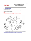
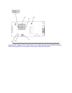
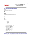
A.2.01 Main Controller Board (AKGI)
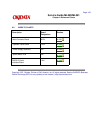
Firmware
05C: CG ROM (Character Generator)
05D: EPROM (Printer Control Program)
NOTE:
If a 4 Mbit Masked ROM is in location 05D, there
SHOULD NOT
be a ROM in location 05C.
However, make sure that jumper SP1 is placed on the A Side.
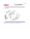
Fuses
F1: soldered - 1 amp. (protects the +40 vdc motor drive circuit)
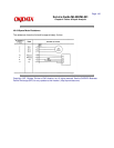
Jumpers
SP1: EPROM Address Select Jumper
A Side:4 Mbit Masked ROM is in location 05D
B Side:CGROM (Location 05C) and EPROM (Location 05D) are installed
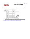
Sensors
SNS1: Rear / Top Feed Paper Out Sensor
SNS3: Bottom Feed Paper Out Sensor
Switches
BASW: Paper Path Select Switch
Test Points
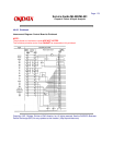
+5 vdc: (Logic, LED Drive Voltage) CN3 - Pins 5 and 6
- 8 vdc: (Serial Interface Line Voltage) CN3 - Pin 11
+8 vdc: (Serial Interface Line Voltage, Comparator Voltage) CN3 - Pin 10
+12 vdc: (Printhead Analog Voltage)CN3 - Pin 9
+40 vdc: (Printhead, Space Motor / Line Feed Motor Drive Voltage)CN3 - Pins 1 and 2
Frame Ground: CN3 - Pins 3 and 4
Logic Ground: CN3 - Pins 7 and 8
ALM: (Alarm Signal to the Power Supply Board) CN3 - Pin 12