


- App. 58 -
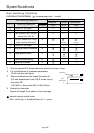
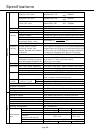
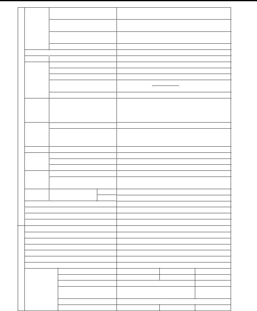
Specifications
Power
Encoder
Built-in
functions
Protective
functions
Monitor
Setting
Position Control
Velocity control
Rotary
encoder
Single-phase
100V system
Single-phase
200V system
3-phase
200V system
Permissible frequency variation
Rotary encoder
Regenerative discharge
Dynamic brake
Auto gain tuning
Electronic gear
(command pulse ratio)
Scale of feedback pulse
Stores past14 errors
including current one.
Alarms marked with *cannot
be stored.
Panel indication
Analogue output (connector pins for monitor)
Selects the items to be measured by using a param-
eter, and measuring range (output impedance of 1kΩ)
Communication
Max. input pulse frequency
Type
Command type
Internal velocity command
Acceleration/deceleration time setting
Rotary encoder phase
A/B
Feedback signal
Z phase
Single-phase, AC100
-
115V
+ 10%
50/60Hz
- 15%
Single-phase, AC200
-
230V
+ 10%
50/60Hz
- 15%
3-phase, AC200
-
230V
+ 10%
50/60Hz
- 15%
Max. ± 5%
IGBT PWM control (sine wave control)
Incremental encoder, 11 wires, 2500 P/r
External regenerative discharge resistor
Active after Main Power-Off, Servo-Off, protective function and limit switch.
Normal and Real time
Calculated as
11-wire incremental encoder: 1 to 2500 P/r
Undervoltage,Overvoltage,Overcurrent,Overload,Regenerative
discharge,Encoder error,Position error,Over speed,command pulse scaler
error,Error counter over flow,EEPROM data error,Alarms (parameter er-
ror, check code error)Overtravel inhibit input error, CPU error etc
Status LED indicator (STATUS), Error LED indicator (ALM CODE)
Velocity monitor: 6V/3000r/min (rated revolution, default)
Torque monitor: 3V/100% (rated torque, default)
Position error pulse number
RS232C
Line driver 500 kpps, Open collector 200 kpps
Line driver and open collector
Quadrature pulse command, CW/CCW pulse command and Pulse/direction command
4 speeds set-up (CW/CCW, Max.10000r/min)
0 to 10s/1000rpm, individual set-up of acceleration and decel-
eration, S-shaped acceleration/deceleration
Line driver output
Output from line driver and open collector
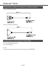
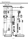
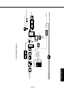
See "System Configuration and Wiring".
Back panel mounting
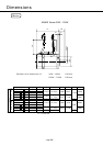
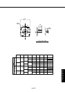
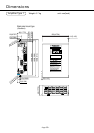
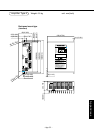
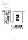
See "Outer Views and Dimensions".
See "Installation".
Amplifier
Control system
Input of control signal
Physical structure
Weight
Working environment
1-10000
x 2
0 -17
1-10000
Motor
Rated speed
Maximum speed
Holding brake
Rotary encoder
Structure (Dust proof and drip proof)
Weight
Working environment
Type
Backlash
Instantaneous max. input revolution
Efficiency
(Torque rating - Revolution rating at 20°C)
Vibration
Structure (Combined with motor)
With reduction
gear
3000r/min
30W-400W:5000r/min.750W:4500r/min
DC24V See "Holding brake built in servo motor".
Incremental encoder, 11 wires, 2500 P/r
IP65 (Except connector, shaft run-through area and reduction gear)
See "Motor outline drawing".
See "Installation".
GH (High accuracy) type GS (Standard) type GL (Popular) type
2-3˙ (Initially) 2-3˙ (Initially) 2-3˙ (Initially)
5000r/min 3600r/min
65% min. 75% min.
V-20
IP44 IP40 IP55