


- 25 -
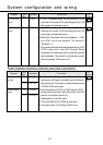
List of Available Components
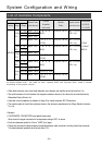
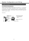
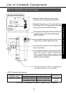
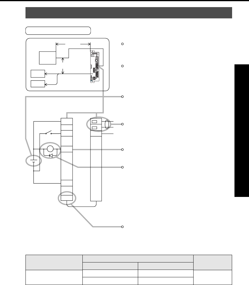
CN I/F Connector (For Controller)
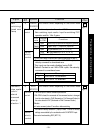
Wiring Instructions
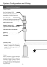
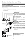
Place the peripheral devices such as the
controller max. 3 m away from the amplifier.
• CN I/F Connector Specifications
• The CN I/F pins assignment is shown in "Optional Parts" in Appendix.
Separate these wiring min. 30 cm from the main
circuit wires. Don't lay these wires in the same
duct of the mains or bundle with them.
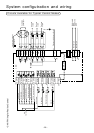
T
he control power (VDC) between COM+ and COM- should
be supplied by the customer (recommended voltage:
+12VDC to +24VDC).
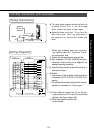
Do not apply power higher than 24V or 50mA to control
signal output terminal.
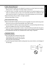
If you directly activate a relay using the control
signal,install a diode in parallel to the relay as
shown in the left figure. Without a diode or with
it but placed in the opposite direction, the
amplifier will be damaged.
Use a shielded twist-paired type for the wiring
of pulse input, encoder signal output, etc.
The Frame Ground (FG) is connected to
an earth terminal in the amplifier.
Preparations and Adjustments
MSDS
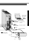
MOTOR
CN
SIG
CN
CN
POWER
CN
I/F
ALARM
POWER
GAIN
RS232C
COM+
GND
1
CN I/F
COM-
FG
V
DC
2
Controller
max. 3 m
min. 30 cm
Power
supply
Motor
Receptacle on the
amplifier side
10226-52A2JL
Connector to controller side
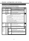
Part description
Solder type plug (Soldering type)
Connector cover
Part No.
10126-3000VE
10326-52A0-008
Manufacturer
Sumitomo
three M