


- 55 -
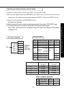
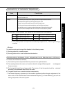
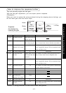
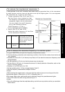
Position loop gain
Pr10
100
50
50
Machine
Ball screw
Timing belt
Rack & pinion
Velocity loop gain
Pr11
50
25
25
Velocity loop integration time constant
Pr12
50
50
200Å`500
Preparations and Adjustments
How to Adjust Gain Manually
Before Adjustment
You may adjust the gains by viewing or hearing the motions and sound of the machine
during operation. But, to adjust the gains more quickly and precisely, you can obtain
quicker and secure adjustment by analog wave form monitoring.
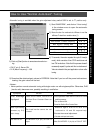
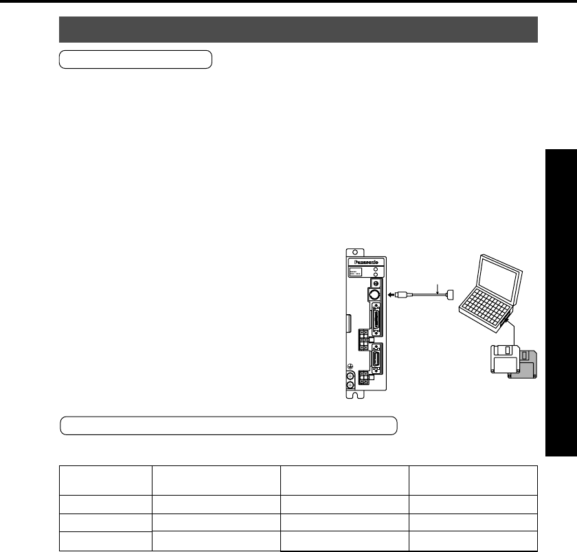
1. Wave form graphic function of PANATERM
“
You can view the graphic information of the command to the motor, actual motor
action (speed, torque and position error) on the computer display screen.
For details, see the instructions of PANATERM
“
.
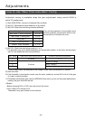
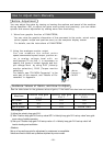
2. Using the analogue monitor output
You can measure the actual motor
speed,commanded speed,torque, position er-
ror in analog voltage level with an
oscilloscope.To do this, it is necessary to
specify the types of output signals and out-
put voltage level by using Pr07 (Velocity
monitor selection), Pr08 (Torque monitor
selection).
For details, see "CN MON Connector" in the
main part of this manual, and "Details of Pa-
rameters" in Appendix.
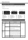
Guidance Values of Gains, and How to Adjust
See the table below for the guidance values of gains, if the inertia ratio has been set correctly.
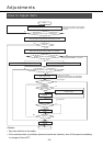
How to adjust
1) Adjust the velocity loop gain Pr11.
2) Take "Position loop gain Pr10 set-up value ÅÖ 2 x Velocity loop gain Pr11 set-up value" as a guid-
ance value of stable operation.
3) Set-up of "Position loop gain Pr10 set-up value > 5 x Velocity loop gain Pr11 set-up value" will
lead to hunting and oscillation.
<Notes>
Set-up of current loop gain for adjustment by customers is unavailable.
Values are fixed to those set up before shipment by motor model.
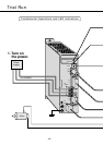
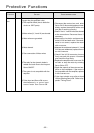
<Note>
Connect to
CN SER.
RS232C cable
MSDS
MOTOR
CN
SIG
CN
CN
POWER
CN
I/F
ALARM
POWER
GAIN
CN
SER