


- 34 -
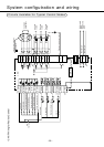
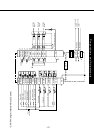
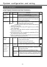
System configuration and wiring
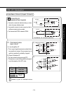
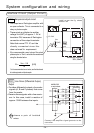
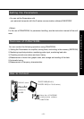
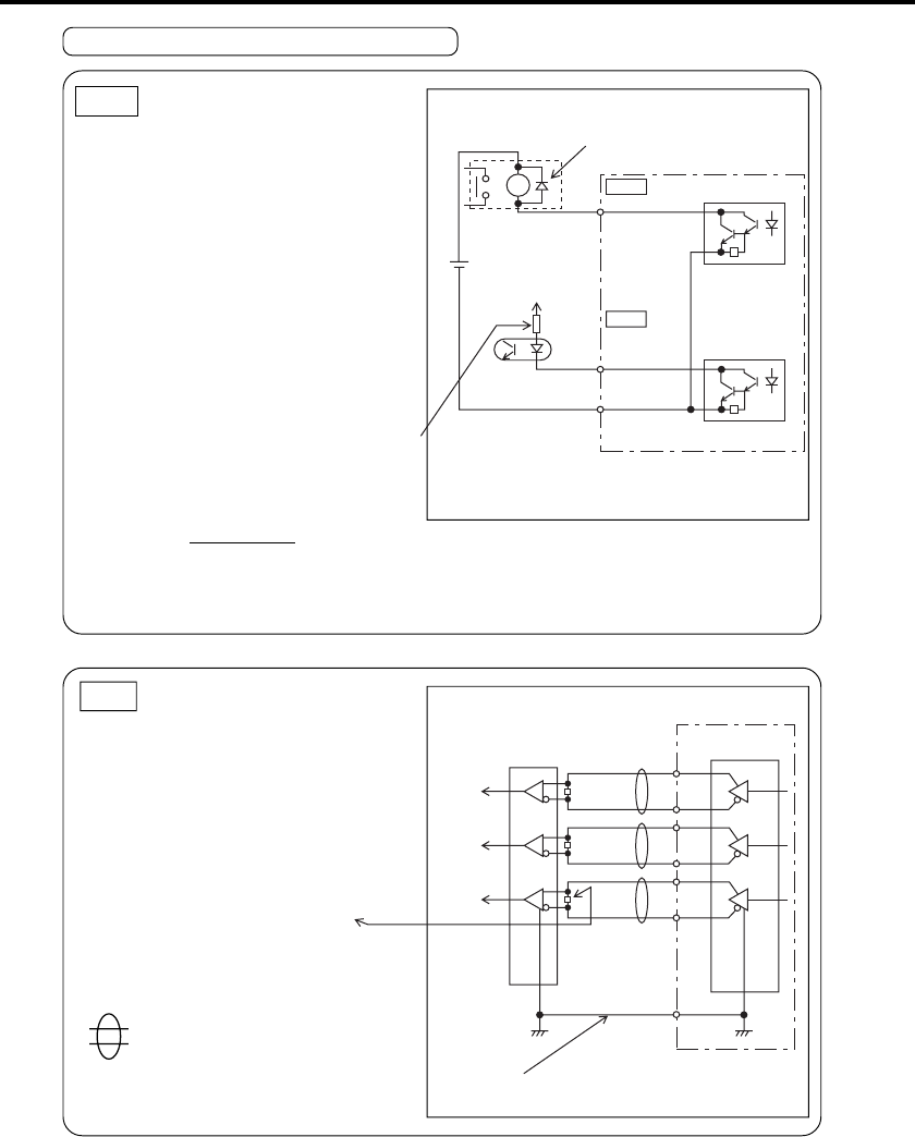
Sequence output circuit
•
This comprises a Darlington amplifier with
an open collector. This is connected to a
relay or photo coupler.
• There exists a collector-to-emitter
voltage V
CE(SAT) of approx. 1.2V at
transistor ON, because of Darlington
connection of the output transistor.
Note that normal TTL IC can't be
directly connected since this
does not meet V
IL requirement.
•
If the recommended current value of the actual
photocoupler is 10mA, calculate the resistance
using the formula below.
For the recommended current value, see the data sheets
of actual equipment and photocoupler.
SO1
Install as per the fig. shows
without fail
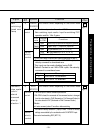
PO1
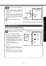
Line Driver (Differential Output)
Output
• Provides differential outputs of encoder
signals (A, B and Z phases) that come
from the scaler.
• Receive these signals with a line receiv-
ers. In this case, install a resistor of
approx. 330Ω between the inputs.
Connect the amplifier signal grounds to the
controller.
R =
V
DC - 2.5
10
[KΩ]
VDC
R [kΩ]
12~24V
SO1
ALM
COM–13
SO1
WARN
or other
signal
Maximum rating:
30V, 50mA
AM26LS32
or equivalent
AM26LS31
or equivalent
A
B
Z
16
15
OA+
OA-
OZ+
OZ-
OB+
OB-
17
19
14
GND
20
18
shows a pair of twisted
wires.
Interface Circuit (Output Circuit)