


- 28 -
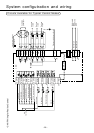
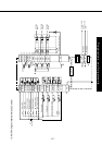
System configuration and wiring
•
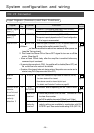
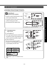
Connect to (+) of an external power supply(12VDC to 24VDC).
•
Use power supply of 12V
±
10%Å`24V
±
10%
•
Connect to (-) of an external power supply(12VDC to 24VDC).
•
The required capacity depends on the I/O circuit configuration.
0.5A or larger is recommended.
•
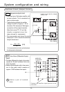
When this signal is connected to COM-, the dynamic brake will be
released and the amplifier is enabled. (Servo-ON).
•
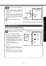
If the COM- connection is kept closed for more than 120 ms,
the alarm status will be cleared.
•
Some alarms cannot be cleared by this input.
For details, see Protective Functions on page 60.
The function differs depending on the control mode.
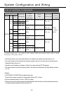
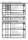
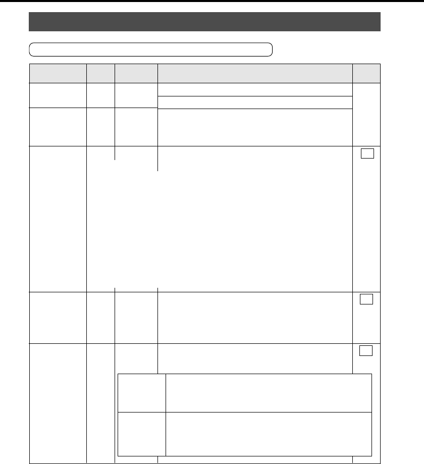
Signal
Pin
Symbol Function
I/F
No.
circuit
Control signal
power
(+)
Control signal
power
(-)
Servo-ON
Alarm
clear
Position error
counter
clear/Internal
command
velocity
selection 2
1
13
2
3
4
COMÅ{
COMÅ|
SRV-ON
A-CLR
CL/
INTSPD2
Å\Å\
SI
page 33
SI
page 33
SI
page 33
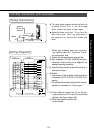
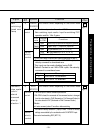
1. This signal becomes effective about two seconds after power on
(see the Timing chart).
2. Don't use this Servo-ON or Servo-OFF signal to turn on or off the
motor. (See App.8)
•
Allow at least 100ms delay after the amplifier is enabled before any
command input is entered.
•
By opening the connection to COM- , the amplifier will be disabled(Servo-OFF) and
the current flow to the motor will be inhibited.
•
Operation of the dynamic brake and clearing action of the position error counter can be
selected using Pr69 (Sequence under Servo-OFF).
<Notes>
Position
control
Internal
velocity
control
• Clears the position error counter. Connect to COM-
to clear the counter.
•
Use Pr4D to select the clear mode (0 Default: level 1: Edge)
•
The internal velocity selection 2 (input) is valid. 4 kinds of
velocity settings are available by combination with DIV/
INTSPD1 input. See control mode setting Pr02 (APP. 16).
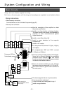
CN I/F Connector
Input Signals (Common) and their Functions