


- 45 -
Preparations and Adjustments
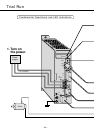
Operation with CN I/F Connected
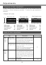
1) Connect CN I/F.
2) Connect the control signal (COM+/-) to the power supply (12 to 24V DC).
3) Turn the main power (amplifier) ON.
4) Check the defaults of the parameters. Control mode setting (Pr2 value: 0).
5) Connect between SRV-ON (CN I/F pin 2) and COM- (CN I/F pin 13) to make Servo-On active. The
motor will be kept excited.
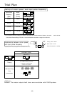
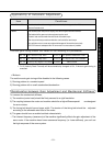
Run at Position Control Mode
1) Set Pr42 (Command Pulse Input Mode Set-Up) according to the output form of the controller. Then
write it down to EEPROM. Then turn the power OFF and then ON again.
2) Send a low-frequency pulse signal from the controller to the amplifier to run the motor at low
speed.
3) Check the motor speed at monitor mode with PANATERM
“
.
• Make sure that the speed is per the set-up.
• Check if the motor stops when the command (pulse) is stopped.
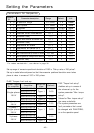
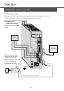
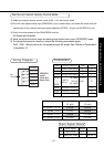
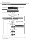
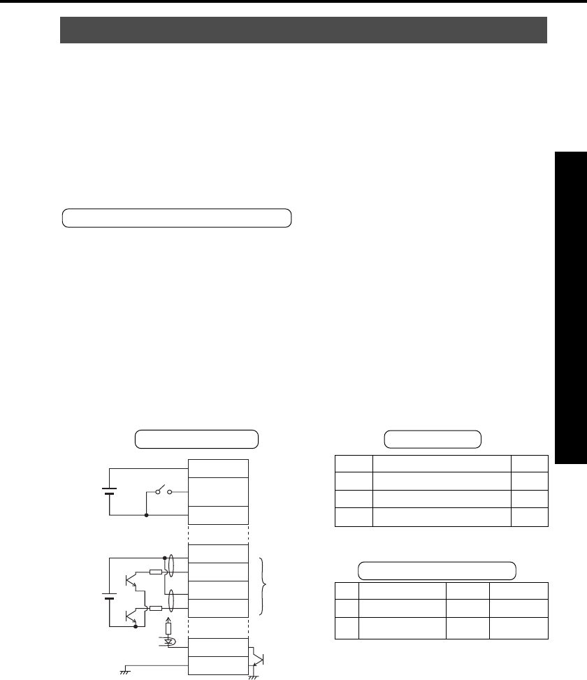
Use the controller to send command pulses.
COM+
1
2
22
23
24
25
21
14
13
SRV-ON
PULS1
PULS2
SIGN1
SIGN2
CZ
GND
COM–
120Ω
120Ω
In case of op
collector for
CW/CCW
pulse inputs
Z-phase
output
for homing
DC
12V~24V
DC
5V
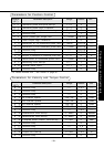
No.
0
A
Input signal
Servo-ON
Counter clear
Monitor display
+ A
---
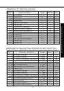
PrNo.
Pr02
Pr04
Pr42
Parameter description
Control mode set-up
Overtravel input inhibit
Command pulse input mode set-up
Value
0
1
1
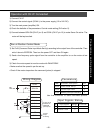
Wiring Diagram
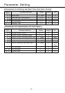
Parameters
Input Signals Status
with PANATERM
“