


- 50 -
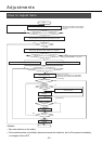
Normal mode
auto gain tuning
Real time
auto gain tuning
Manual gain tuning
Gain tuning using the rotary
switch for gain adjustment
Gain set-up: low
Gain set-up: high
+Feed forward set-up
Adjustments
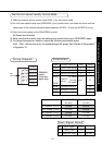
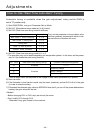
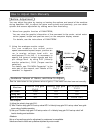
Purposes of Gain Adjustment
In case of the servo motor, the motor is required to act per any command without any
time delay, or without missing any commands. To ensure this, gain adjustment is
necessary.
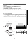
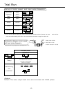
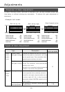
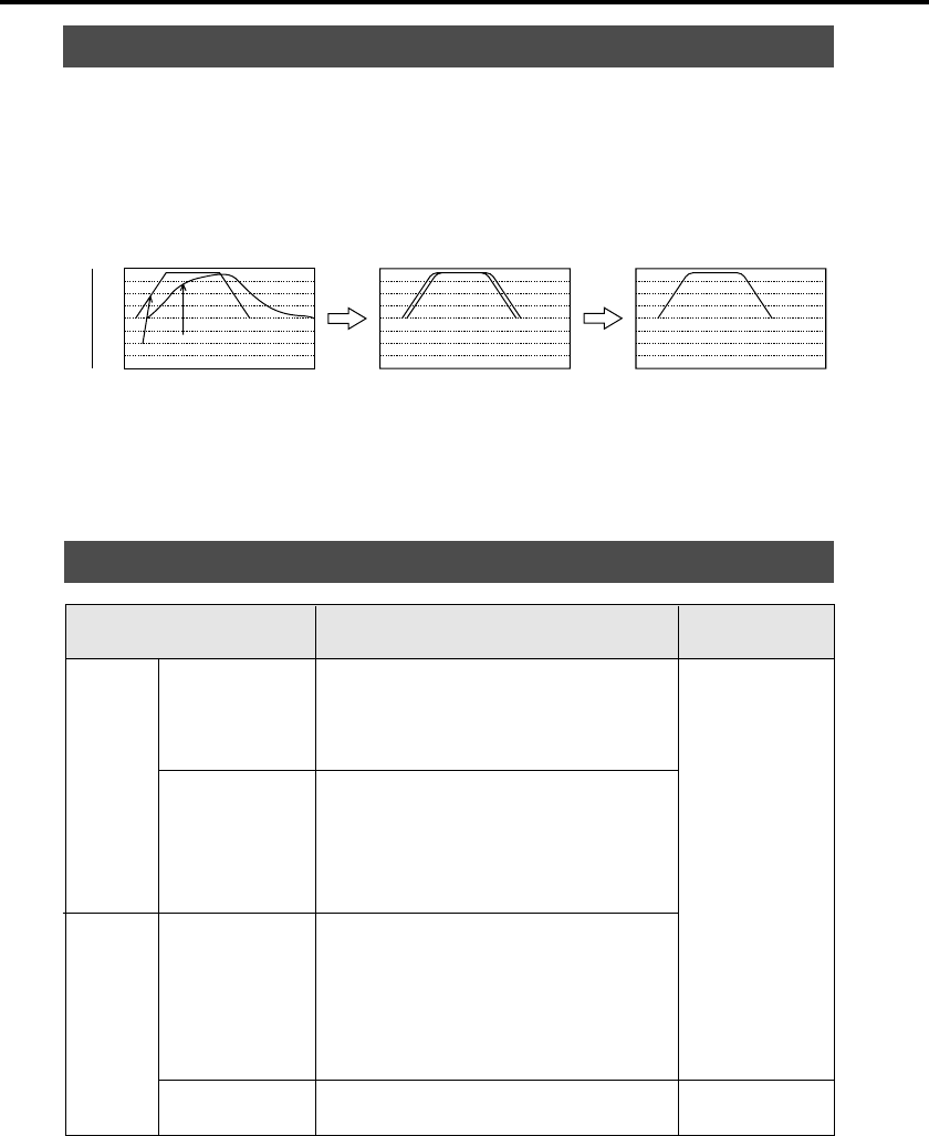
<Example: ball screw>
Position loop gain
: 20
Velocity loop gain
: 100
Velocity loop integration time constant
: 50
Velocity feed forward
: 0
Inertia ratio
: 100
Position loop gain
: 100
Velocity loop gain
: 50
Velocity loop integration time constant
: 50
Velocity feed forward
: 0
Inertia ratio
: 100
Position loop gain
: 100
Velocity loop gain
: 50
Velocity loop integration time constant
: 50
Velocity feed forward
: 50
Inertia ratio
: 100
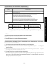
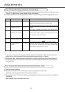
Types of Gain Adjustment
Type Description
Accelerate and decelerate the motor per the preset
(internally fixed) patterns to calculate the load inertia
from the required torque. Then automatically define
appropriate gains according to the inertia.
During an actual operation, calculate the load inertia in
real time. Then automatically define appropriate gains
according to the inertia.
The gains will be automatically adjusted against the
fluctuation of load inertia during
operation.
You can manually adjust the necessary gains to obtain
the most appropriate action by monitoring command to
the amplifier, motor speed, torque and position error as
the monitor signals (SP, IM), or using the optional
communication software, PANATERM
“
(especially with its
graphic function).
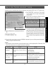
Gain adjustment is available by digital setting with
the rotary switch.
Auto-
matic
adjust-
ment
Manual
adjust-
ment
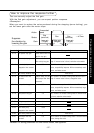
Gain set value of rotary
switch for gain adjustment
1-9
0
+2000
-2000
0
0.0 375250125 0.0 375250125 0.0 375250125
{r/min}
+2000
-2000
0
{r/min}
Actual velocity
Command Speed