


37
Terminal Duration Remarks
Alarm Output 1 to
32
Until reset Open Collector
output, 16 V,
100 mA maximum
Alarm Recover
Input 1 to 16
100 or more ms Non-voltage make
contact output
Time Adjust
Output
1 second Open Collector
output, 16 V,
100 mA maximum
Time Adjust Input 100 or more ms Non-voltage make
contact input
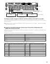
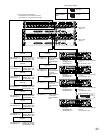
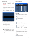
■ System Status Check
During connection procedures, system status can be
checked on 4 monitors.
The following examples are procedures to display the sys-
tem status on Monitor 1 to 4.
● WV-CU950/650
1. Select one of Monitor 1 to 4. (Refer to p. 21 Monitor
Selection.)
2. Press the MENU button repeatedly until "System Status"
appears on the LCD.
3. Press the F1 button. SYSTEM STATUS will be displayed
on Monitor 1 to 4.
Note: SYSTEM STATUS is displayed on a set of 4 monitors
(Monitor 5 to 8, Monitor 9 to 12...Monitor 29 to 32).
● WV-CU360C/CJ
1. Select one of Monitor 1 to 4. (Refer to p. 21 Monitor
Selection.)
2. Press the OSD and SYS S buttons at a time. SYSTEM
STATUS will be displayed on Monitor 1 to 4.
Note: SYSTEM STATUS is displayed on a set of 4 monitors
(Monitor 5 to 8, Monitor 9 to 12...Monitor 29 to 32).
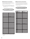
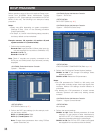
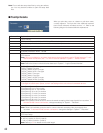
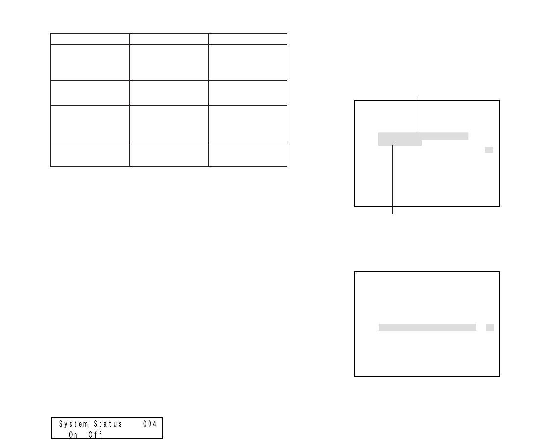
Display example of SYSTEM STATUS
<Monitor 1>
<Monitor 4>
MON:
Monitor number
LCN: Camera number or recorder number
MODE: Display mode of the monitor
• SETUP: System Setup
• HISTORY: Alarm History Display
KB: System controller or PC
OPE: User ID of the operator or timer event No.
PRI: Operator priority
•When SETUP MENU is displayed, "0" appears on
this area.
•During monitor lock, this area is highlighted.
Notes:
• Even while SYSTEM STATUS is being displayed on
monitors, normal operations and alarm control are avail-
able. However, you cannot check the camera or record-
ed images because black screen is displayed. It is rec-
ommended to use these monitors only to check SYS-
TEM STATUS.
• Up to 100 records of SYSTEM STATUS are saved in the
system. These records can be transmitted between PC
and this unit. (Periodical transmission is also available.)
For transmission, perform the serial command settings
in "Communication" – "Serial Command" of WJ-SX650
Series Administrator Console.
• To transmit SYSTEM STATUS records from the PC, refer
to Serial (RS-232C) Connector Command Reference
(PDF file on the supplied CD-ROM).
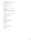
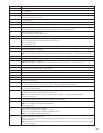
SYSTEM STATUS
MON LCN MODE KB OPE PRI
01 001
02 002 K1-1 123 01
03 200 03
04 030 /T001 99
05 100 G08 PC 999 14
06 SETUP K1-4 5 00
07 HISTORY K3-2 10 02
08 R16 505 03
LCN:LOGICAL CAMERA NUMBER
LCN, MODE, KB and OPE parameters are highlighted
for monitors during the alarm mode status.
LCN and MODE parameters are highlighted for monitors
during the alarm ACK status.
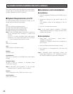
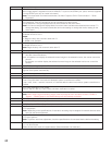
SYSTEM STATUS
MON LCN MODE KB OPE PRI
25
26 075 PSD 48 02
27 105 T32 /T128 60
28 002 T01 K6-3 3 05
29 301 G32 12345 10
30 401 G32 12345 10
31 501 G32 K8-4 12345 10
32 999
LCN:LOGICAL CAMERA NUMBER