


31
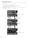
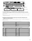
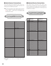
LCN LCN
1 to 16
17 to 32
33 to 48
49 to 64
65 to 80
81 to 96
97 to 112
113 to 128
Recorder number (Unit Address (System) Recorder number (Unit Address (System)
1
2
3
4
5
6
7
8
129 to 144 9
145 to 160 10
161 to 176
177 to 192
11
12
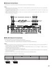
VIDEO OUT 3
VIDEO OUT 4
VIDEO OUT 2
IN X-2
VIDEO OUT 1
ALARM IN
IN X-1
16
32
15
31 30
14 13
29 28
12 11
27 26
10 9
25
CAMERA IN
24
87
23 22
65
21 20
43
19 18
21
17
EXTENSION 3 IN
EXTENSION 2 IN
4
MODE
RS485 (CAMERA) RS485 (CAMERA)
3
MODE MODE MODE
2
1
IN C-3
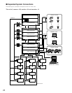
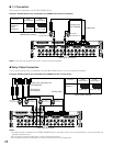
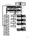
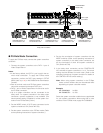
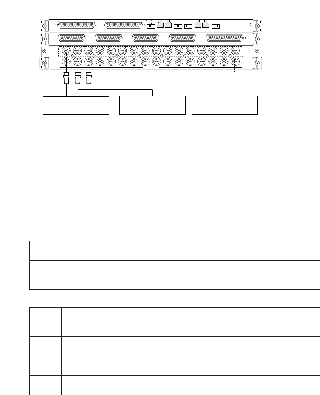
Unit Address (System): 1
• • • Up to 16 recorders
Unit Address (System): 2
Unit Address (System): 3
Video output
connector
CAMERA IN 17 to 32
Recorder
Recorder Recorder
Video input
board
Up to 16 unused connectors
(CAMERA IN 17 to 32) are required
for recorder connections.
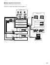
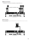
To display recorder images on external monitors directly connected to recorders
When using all the CAMERA IN connectors of video input boards for camera connections, external monitors can be connected
directly to recorders.
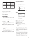
Note: Recorder settings are performed in RECORDER of SETUP MENU (refer to p. 87) or "System" – "Recorder" of WJ-SX650
Series Administrator Console.
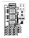
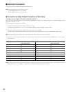
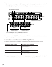
● Loop-thru Connection between Camera Input Connectors of Recorders and
VIDEO OUT Ports of this Unit
VIDEO OUT 1 to 4 ports are connected to the camera input connectors of recorders. For connection, use D-sub/BNC Video
Cable WJ-CA68 (Option).
The following is the association of camera input connectors with video output connectors.
Camera input connectors or recorders
1 to 8
9 to 16
17 to 24
25 to 32
Video output connectors (VIDEO OUT 1 to 4) of this unit
VIDEO OUT 1
VIDEO OUT 2
VIDEO OUT 3
VIDEO OUT 4
The following is the association of LCN's and recorder numbers for the loop-thru connections.
193 to 208 13
209 to 224 14
225 to 240 15
241 to 256 16