


53
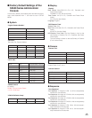
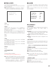
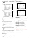
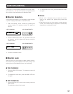
● VD2/DATA/CABLE COMPENSATION
Menu
• INPUT BOARD
Select a video input board from 1 to 8. (The factory default
is 1.
• VD2
Select ON or OFF. (The factory default is ON.)
ON: Sends the VD2 timing pulse with the camera output
signal.
OFF: Not sends the VD2 timing pulse with the camera out-
put signal.
• DATA
Select ON or OFF. (The factory default is ON.)
ON: Sends the control data with the camera output signal.
OFF: Not sends the control data with the camera output
signal
• CABLE
Perform the settings to compensate for the video signal
transmission loss from the camera (cable compensation)
according to the cable lengths. (The factory default is S.)
S: Less than 500 m
M: 500 m to 900 m
L: 900 m to 1 200 m
Note: When supplying video input signals from recorders
or using cameras of other manufacturers, set DATA to
OFF.
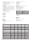
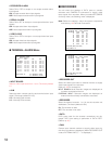
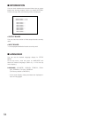
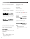
● RS485 CAMERA Menu
• INPUT BOARD
Select a video input board from 1 to 8. (The factory default
is 1.
• RS485
Select the RS-485 (CAMERA) port connecting RS-485 cam-
eras. (The factory default is no settings.)
CAM001 to 032: 1 to 4 (INPUT BOARD=1)
CAM033 to 064: 5 to 8 (INPUT BOARD=2)
CAM065 to 096: 9 to 12 (INPUT BOARD=3)
CAM097 to 128: 13 to 16 (INPUT BOARD=4)
CAM129 to 160: 17 to 20 (INPUT BOARD=5)
CAM161 to 192: 21 to 24 (INPUT BOARD=6)
CAM193 to 224: 25 to 28 (INPUT BOARD=7)
CAM225 to 256: 29 to 32 (INPUT BOARD=8)
• ADR
Select the unit address for the connected RS-485 cameras.
Note: RS485 is not available for camera channels accept-
ing video input signals from recorders. To activate RS-
485 camera connections, change the settings in
RECORDER. (Refer to p. 87.)
530 VD2/DATA/CABLE COMPENSATION 1 of 2
INPUT BOARD=8
CAM VD2 DATA CABLE CAM VD2 DATA CABLE
225 ON OFF S 233 ON OFF S
226 ON OFF M 234 ON OFF S
227 ON OFF L 235 ON OFF S
228 ON OFF S 236 ON OFF S
229 ON OFF M 237 ON ON S
230 ON OFF L 238 ON ON S
231 ON OFF S 239 ON ON S
232 ON OFF S 240 ON ON S
CAM=CAMERA IN
DATA:CAMERA CONTROL SIGNAL
540 RS485 CAMERA 1 of 2
INPUT BOARD=8
CAM RS485 ADR CAM RS485 ADR
225 29 1 233 30 1
226 29 2 234 30 2
227 29 3 235 30 3
228 29 4 236 30 4
229 29 5 237
230 29 6 238
231 29 7 239
232 29 8 240
COMMUNICATION STATUS 19200/8/ NONE/1
CAM=CAMERA IN RS485=RS485(CAMERA)
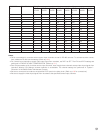
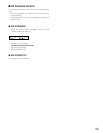
530 VD2/DATA/CABLE COMPENSATION 2 of 2
INPUT BOARD=8
CAM VD2 DATA CABLE CAM VD2 DATA CABLE
241 ON OFF S 249 OFF OFF S
242 ON OFF M 250 OFF OFF S
243 OFF OFF L 251 OFF OFF S
244 OFF OFF S 252 OFF OFF S
245 OFF OFF M 253 OFF OFF S
246 OFF OFF L 254 OFF OFF S
247 OFF OFF S 255 OFF OFF S
248 OFF OFF S 256 OFF OFF S
CAM=CAMERA IN
DATA:CAMERA CONTROL SIGNAL
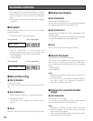
540 RS485 CAMERA 2 of 2
INPUT BOARD=8
CAM RS485 ADR CAM RS485 ADR
241 31 1 249
242 32 1 250
243 251
244 252
245 253
246 254
247 255
248 256
COMMUNICATION STATUS 19200/8/ NONE/1
CAM=CAMERA IN RS485=RS485(CAMERA)