28
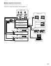
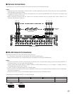
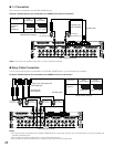
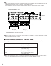
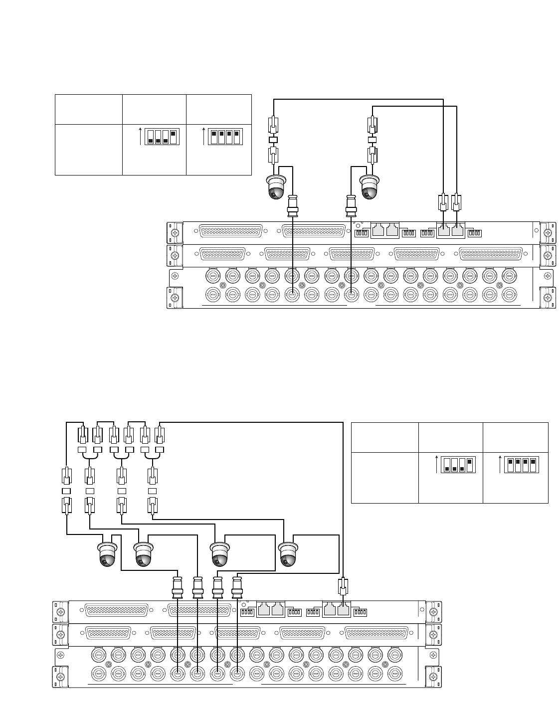
● 1:1 Connection
One camera is connected to one RS-485 (CAMERA) port.
Example: RS-485 cameras are connected to the CAMERA IN 9 and 12 connectors.
Note:
Do not use unit numbers other than 1 to 8 for individual cameras.
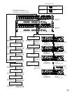
● Daisy Chain Connection
Two or more cameras can be connected to one RS-485 (CAMERA) port. Up to 8 cameras are available.
Example: RS-485 cameras are connected to the CAMERA IN 9 to 12 connectors
VIDEO OUT 3
VIDEO OUT 4
VIDEO OUT 2
IN X-2
VIDEO OUT 1
ALARM IN
IN X-1
16
32
15
31 30
14 13
29 28
12 11
27 26
10 9
25
CAMERA IN
24
87
23 22
65
21 20
43
19 18
21
17
EXTENSION 3 IN
EXTENSION 2 IN
4
MODE
RS485 (CAMERA) RS485 (CAMERA)
3
MODE MODE MODE
2
1
IN C-3
ON
1234
ON
1234
Connector
RS485
(CAMERA) 1
RS485
(CAMERA) 2
4-wire
communication
2-wire
communication
(SW#4: ON) (SW#1 to 4: ON)
MODE switch settings
Video input rear boards
Junction Unit
WV-CA48/JN
RS-485 cable
Unit number: 1
Line termination: ON
Unit number: 1
Line termination: ON
VIDEO OUT 3
VIDEO OUT 4
VIDEO OUT 2
IN X-2
VIDEO OUT 1
ALARM IN
IN X-1
16
32
15
31 30
14 13
29 28
12 11
27 26
10 9
25
CAMERA IN
24
87
23 22
65
21 20
43
19 18
21
17
EXTENSION 3 IN
EXTENSION 2 IN
4
MODE
RS485 (CAMERA) RS485 (CAMERA)
3
MODE MODE MODE
2
1
IN C-3
ON
1234
ON
1234
Connector
RS485
(CAMERA) 1
4-wire
communication
2-wire
communication
(SW#4: ON) (SW#1 to 4: ON)
MODE switch settings
Video input rear boards
RS-485 cable
Junction Unit
WV-CA48/JN
Daisy Chain Connection Kit
WV-CA48/10K
Unit number: 4
Line termination: ON
Unit number: 3
Line termination: OFF
Unit number: 2
Line termination: OFF
Unit number: 1
Line termination: OFF
Notes:
•Among cameras connected to an RS485 (CAMERA) port in the daisy chain (4-wire communication), only one camera can
activate camera alarms.
•Do not use unit numbers other than 1 to 8 for individual cameras.
• Do not set the same unit numbers for more than one camera in an RS-485 chain.


