


44
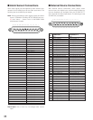
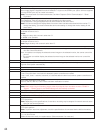
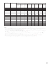
Reference No.
46
47
48
49
50
51
52
53
54
1 to 1024: Alarm Output number
Alarm output signal is supplied from the ALARM OUT 1/2 port or the SERIAL port. (65 to 1024 are supplied
from the SERIAL port only as a serial command.)
Note: To activate serial command transmission, set Alarm Output to ON in "Communication" – "Serial
Command".
Spot: Only the spot images can be activated for the alarm event.
Tour Sequence: Only tour sequences can be activated for the alarm event.
Group Sequence: Only group sequences can be activated for the alarm event.
Note: You cannot change the Display Mode if an alarm event has been associated with the monitor. To
change the setting, you need to delete the alarm event setting or change the monitor setting for the
alarm event.
Available digits: 5 or less
Available numerics: 0 to 9
Notes:
• Begin the entry with a numeric other than "0".
• 99999 is not available.
Available digits: 5 or less
Available numerics: 0 to 9
Note: Begin the entry with a numeric other than "0".
1 to 5: Level
View & Operate: An operator can display the selected camera image on the selected monitor. The operator
can also control the camera.
View: An operator can display the selected camera image on the selected monitor, but cannot control the
camera.
--: The operator can neither display the selected camera image on the selected monitor nor control the
camera.
User ID: Select a registered User ID.
1, 3, 5, 10, 30, or 60 min: If no operations are performed during this period in the login status, the operator
logs out of the system automatically.
1 to 2: Video output board No.
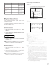
55 Available parameters: 1 to 4096
56 OFF: Alarm occurrence is not notified.
0 sec: Every time alarm occurrence is detected, system controllers are notified.
1 sec, 3 sec, 5 sec: 1 second, 3 second, or 5 seconds after the alarm occurrence, system controllers are
notified.
57
58
59
60
61
62
63
64
OFF: Alarm notification is not retried.
100 ms, 200 ms, 400 ms, 1 sec: Period until alarm notification is retried
0 to 16: Total recorder number
Note: When camera input channels to supply video input signals from recorders are set to "RS485" in
"System" – "RS485 Camera", the RS485 settings are automatically cancelled.
0 to 1: Total number of PS·Data system controllers
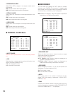
ON, OFF, AUTO, _: B/W setting
PATROL1(S) to PATROL4(S) , _: Patrol picture quality
ON: Perform
OFF: Not perform
Note: Depending on the specifications of recorders, recording may be stopped for several seconds at the
timing of auto time adjustment.
ON: Perform
OFF: Not to perform
Note: To perform auto time adjustment, check the specifications of connected device before the setting.
OFF: Not notify
1, 5, 10, 30 or 60 sec
Select the interval to notify the system status. (Recommended: 5 or more sec)
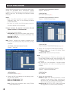
Explanation