


50
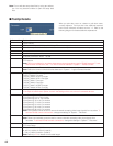
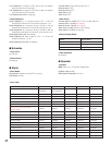
• RECORDER ALARM
Select ON or OFF to accept or not accept recorder alarm
input signals.
ON: Accepts recorder alarm input signals.
OFF: Not accepts recorder alarm input signals.
• SERIAL ALARM
Select ON or OFF to accept or not accept serial alarm input
signals.
ON: Accepts serial alarm input signals.
OFF: Not accepts serial alarm input signals.
• VIDEO LOSS
Select ON or OFF to accept or not accept video loss input
signals.
ON: Accepts video loss input signals.
OFF: Not accepts video loss input signals.
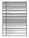
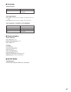
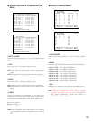
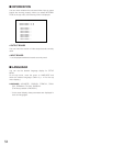
● TERMINAL ALARM Menu
• INPUT BOARD
Select a video input board from 1 to 8. (The factory default
is 1.
• ALM
Select the alarm contact type for each terminal alarm input
signal. (The factory default is N.O.)
N.O.: Normally Open contact
N.C.: Normally Close contact
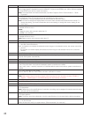
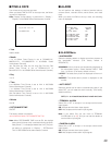
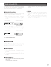
■ RECORDER
You will check the settings of DATA ports to connect
recorders and CAMERA IN connectors to supply video
input signals from recorders. When you select RECORDER
on the top menu, the following menu is displayed.
Note: Before the settings, check the system composition
and refer to p. 63 Recorder Connection.
• RECORDER OUT
Select the video input board or external monitor to supply
video input signals from recorders.
Refer to p. 63 for connections.
INPUT BOARD1 to 8: Recorder images are displayed on
monitors connected to the unit.
EXTERNAL INPUT: Recorder images are displayed on
external monitors directly connected to recorders.
• RECORDER
Select the desired recorder. 1 to 16 are the recorder unit
addresses. (The factory default is ON.)
ON: The recorder is used.
OFF: The recorder is not used.
• DATA
DATA ports used for the recorder connections are dis-
played. DATA port setting is performed in DATA PORT.
(Refer to p. 90.)
• CAM
Camera input channel numbers to supply video input sig-
nals from recorders are displayed. (When RECORDER OUT
is set to EXTERNAL INPUT, "- -" is displayed.)
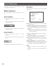
330 TERMINAL ALARM
INPUT BOARD=8
ALM ALM ALM ALM
225
N.O.
233
N.C.
241
N.O.
249
N.C.
226
N.O.
234
N.C.
242
N.O.
250
N.C.
227
N.O.
235
N.C.
243
N.O.
251
N.C.
228
N.O.
236
N.C.
244
N.O.
252
N.C.
229
N.O.
237
N.C.
245
N.O.
253
N.C.
230
N.O.
238
N.C.
246
N.O.
254
N.C.
231
N.O.
239
N.C.
247
N.O.
255
N.C.
232
N.O.
240
N.C.
248
N.O.
256
N.C.
ALM=ALARM IN
N.O.
:NORMALLY OPEN
N.C.
:NORMALLY CLOSE
400 RECORDER 1 of 2
RECORDER OUT INPUT BOARD8
RECORDER DATA CAM
01 HDR1 256 ON
02 HDR1 255 ON
03 HDR1 254 ON
04 HDR1 253 ON
05 HDR2 252 ON
06 HDR2 251 ON
07 HDR2 250 ON
08 HDR2 249 ON
DATA=DATA(TMNL/PSD/HDR)
CAM=CAMERA IN
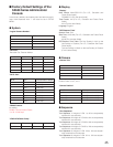
400 RECORDER 2 of 2
RECORDER OUT INPUT BOARD8
RECORDER DATA CAM
09 HDR3 248 ON
10 HDR3 247 ON
11 HDR3 246 ON
12 HDR3 245 ON
13 HDR4 244 ON
14 HDR4 243 ON
15 HDR4 OFF
16 HDR4 0FF
DATA=DATA(TMNL/PSD/HDR)
CAM=CAMERA IN