


13
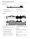
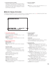
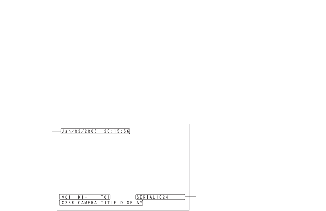
■ Monitor Display Information
The following are the details on terminal mode operations. For PS·Data operations, refer to p. 48 OPERATION (OTHER THAN
THE TERMINAL MODE) or the operating instructions of system controllers.
q Time and Date Information
Current time and date are displayed.
During daylight saving time (summer time), "
∗" is dis-
played beside the time.
Example: Aug/02/2005 ∗20:15:56
Note: While a recorder is being selected, time and date
are not displayed.
w Monitor Status Information
Monitor number
M01 to 32: Monitor number
Note: During monitor lock, monitor number is highlight-
ed.
Controller number
Displays a device that selects and controls the monitor.
K1-1 to 8-4: Terminal mode system controller
(Example: For K8-4, "8" means the terminal (TMNL)
number and "4" means the controller number of sys-
tem controller.)
PSD: PS·Data mode system controller
PC: PC connected to the SERIAL port
/T001 to 128: Timer event
Sequence number
Displays the active sequence number.
T01 to 32: Tour sequence number
G01 to 32: Group sequence number
Note: During sequence pause, "P" is displayed beside
the sequence number.
e Camera Information
Camera number
C001 to 999: Camera number
R01 to 16: Recorder number
Camera title
Displays the registered camera title.
Camera title setting is performed in "Camera" – "Camera
Title" of WJ-SX650 Series Administrator Console.
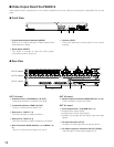
r Event Information
TERMINAL001 to 256: Terminal alarm has occurred.
(Example: For TERMINAL001, "001" means the
number of alarm input signal accepted by the
ALARM IN port of video input board.)
CAMERA001 to 099: Camera alarm has occurred.
(Example: For CAMERA001, "001" means the num-
ber of camera supplying an alarm input signal to
the unit.)
RECORDER001 to 999: Recorder alarm has occurred.
(Example: For RECORDER001, "001" means the
number of camera associated with the recorder
supplying an alarm input signal to the unit.)
SERIAL0001 to 1024: Serial alarm has occurred.
(Example: For SERIAL0001, "0001" means the serial
command alarm input number.)
VIDEO LOSS001 to 999: Video loss has occurred.
(Example: For VIDEO LOSS001, "001" means the num-
ber of camera to which video loss has occurred)
SUSPEND: Alarm is suspended.
r
q
w
e
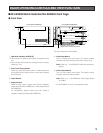
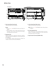
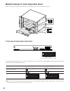
!3 VS Output Connector (VS OUT)
Supplies VS output signals to external devices. While !1
is accepting a VS input signal, !3 supplies an output
signal synchronizing the VS input signal. While
!1 is not
accepting the VS input signal,
!3 supplies an internal
synchronization output signal.
!4 Serial Port (SERIAL)
Connects to a PC.
Note: When q is set as Video Output Board 2, r, !1,
!2, !3, and !4 are not available.