


32
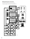
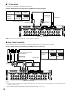
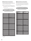
Recorder's unit address (System)
VIDEO OUT 3
VIDEO OUT 4
VIDEO OUT 2
IN X-2
VIDEO OUT 1
ALARM IN
IN X-1
16
32
15
31 30
14 13
29 28
12 11
27 26
10 9
25
CAMERA IN
24
87
23 22
65
21 20
43
19 18
21
17
EXTENSION 3 IN
EXTENSION 2 IN
4
MODE
RS485 (CAMERA) RS485 (CAMERA)
3
MODE MODE MODE
2
1
IN C-3
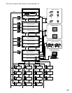
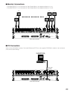
BNC cable
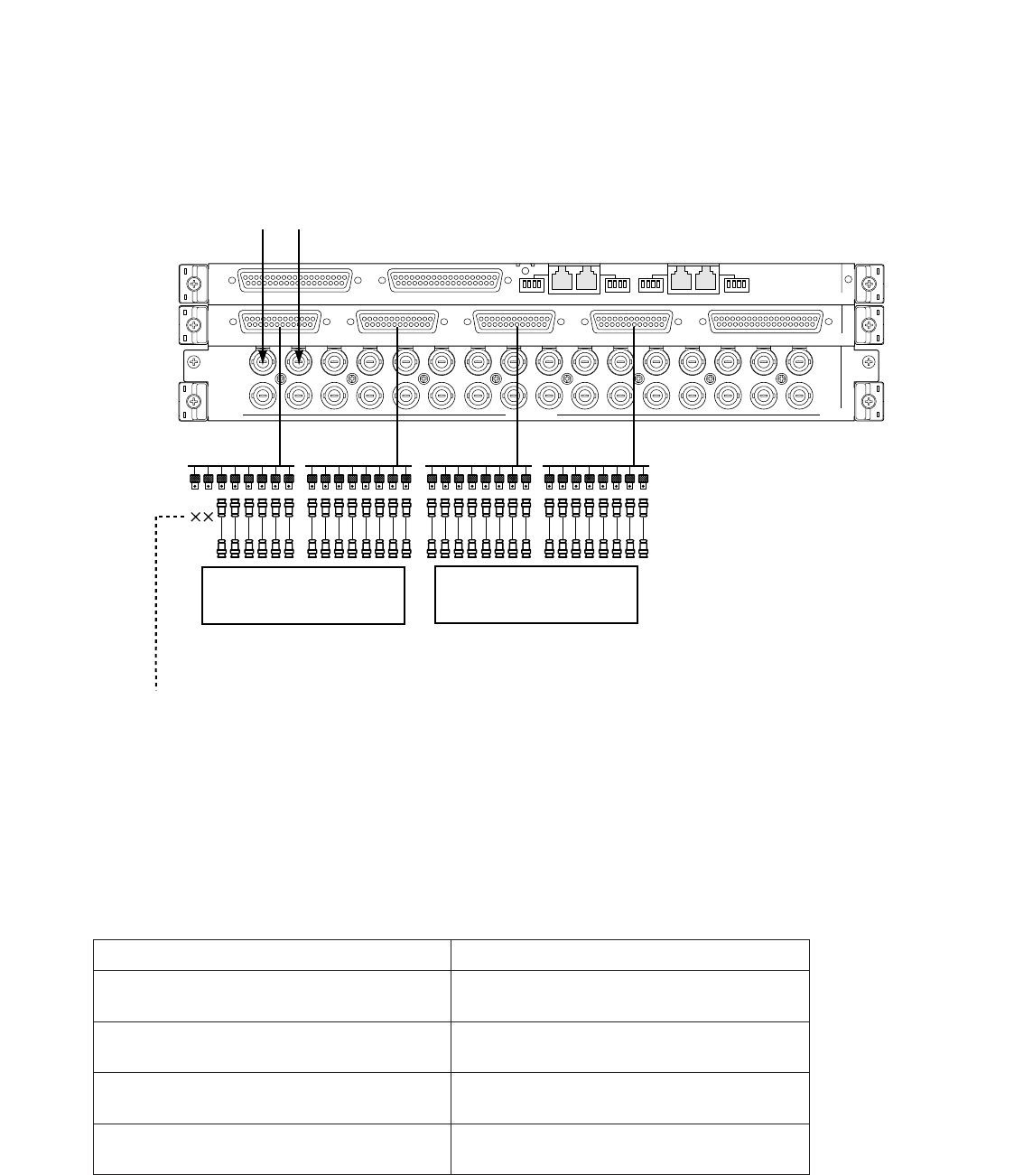
D-sub/BNC Video Cable WJ-CA68
32 3130 25 24 17 16 9 8 1
Recorder
Recorder
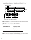
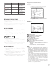
Video input signals are supplied from
recorders to the CAMERA IN 31 and 32.
Video input
board
LCN: 17 to 32
Unit Address (System): 2
LCN: 1 to 16
Unit Address (System): 1
Do not connect VIDEO OUT of the unit to CAMERA IN of recorders if these
camera channels supply video output signals from recorders.
Note: Do not connect the VIDEO OUT ports of the unit to the CAMERA IN connectors of recorders if these camera channels
supply video output signals from recorders.
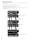
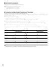
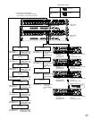
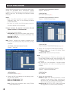
● Connection between Recorders and Video Input Boards
By connecting recorders to the DATA ports of this unit, recorder control becomes available from system controllers.
Note: You can change data port settings according to the connected devices. Setting changes are performed in "System" –
"DATA Port" of WJ-SX650 Series Administrator Console or DATA PORT (refer to p. 90) of SETUP MENU.
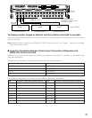
1 to 4
5 to 8
9 to 12
13 to 16
DATA port for recorder connection
DATA 3 port of Video Output Board 1
(Factory default: HDR1)
DATA 4 port of Video Output Board 1
(Factory default: HDR2)
DATA 3 port of Video Output Board 2
(Factory default: HDR3)
DATA 4 port of Video Output Board 2
(Factory default: HDR4)
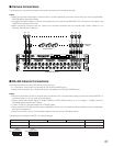
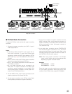
Notes:
•When changing connections, perform the LCN settings of camera channels supplying video input signals to recorders. The
LCN settings are performed in "System" – "Recorder" – "Logical Camera Number".
• Camera input signals are looped through the unit. Monitor display information (camera title, etc.) are not recorded.