


12
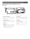
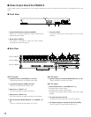
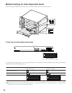
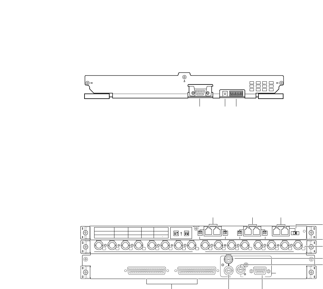
■ Video Output Board WJ-PB65M16
Video output board is composed of a main board (installed into the front side) and rear boards (x 3)(installed into the rear
side).
● Front View
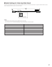
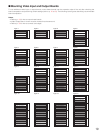
q Output Mode Selection Switches (MODE)
Refer to p. 52 Switch Settings for Video Output Board
(Main Board) for details.
w Reset Switch (RESET)
This button is pressed to reset the whole system.
(Equivalent to power off and on)
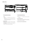
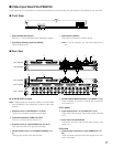
● Rear View
OUT X-3 board
r Extension Ports 1 (EXTENSION 1: IN, OUT)
These ports connect to an optional card cage.
t Termination Selector (TERM: ON, OFF)
Turns on or off the line termination of r.
y Data ports 1, 2 (DATA 1, 2)
Each port connects to system controllers.
u Data ports 3, 4 (DATA 3, 4)
Each port connects to system controllers or recorders.
i Rear Termination MODE Switches 1 to 4 (MODE 1 to
4)
Turns on or off the line termination of y and u.
OUT X-2 board
o Monitor Output Connectors (MONITOR OUT 1 to 16)
These connectors connect to monitors.
OUT X-1 board
!0 Alarm Output Ports 1,2 (ALARM OUT 1, 2)
• Supplies alarm output signals.
• Accepts alarm recover input signals.
• Supplies and accepts the time adjust input and output
signals.
!1 VS Input Connector (VS IN)
Accepts a VS input signal from an external device.
!2 VS Output Loop-thru Connector (VS OUT (THRU))
Loops through VS input signals supplied to !1.
e Test port (TEST)
This port is used only for factory tests. Do not connect
anything.
RESET
TEST
MODE
qwe
OUT X-2
12345678
MONITOR OUT
910111213141516
EXTENSION 1
TERM.
OFF
ON
OUT
IN
OUT X-3
MODEMODE
DATA
12
MODEMODE
DATA
34
TERM.OFF
ON
MODE
TERM.ON
MODE
DATA 4
HDR4/TMNL8
HDR2/TMNL4
DATA 3
HDR3/TMNL7
HDR1/TMNL3
DATA 2
TMNL6
TMNL2
DATA 1
TMNL5
TMNL1/PS DATA
Video Output Board 2
Video Output Board 1
OUT X-1
ALARM OUT 2
ALARM OUT 1
SERIAL
VS OUT
VS IN
VS OUT
(THRU)
Video Output Board 1 Only
ryu
t
i
o
!0
!1
!3
!4!2
OUT X-3 board
OUT X-2 board
OUT X-1 board