86
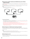
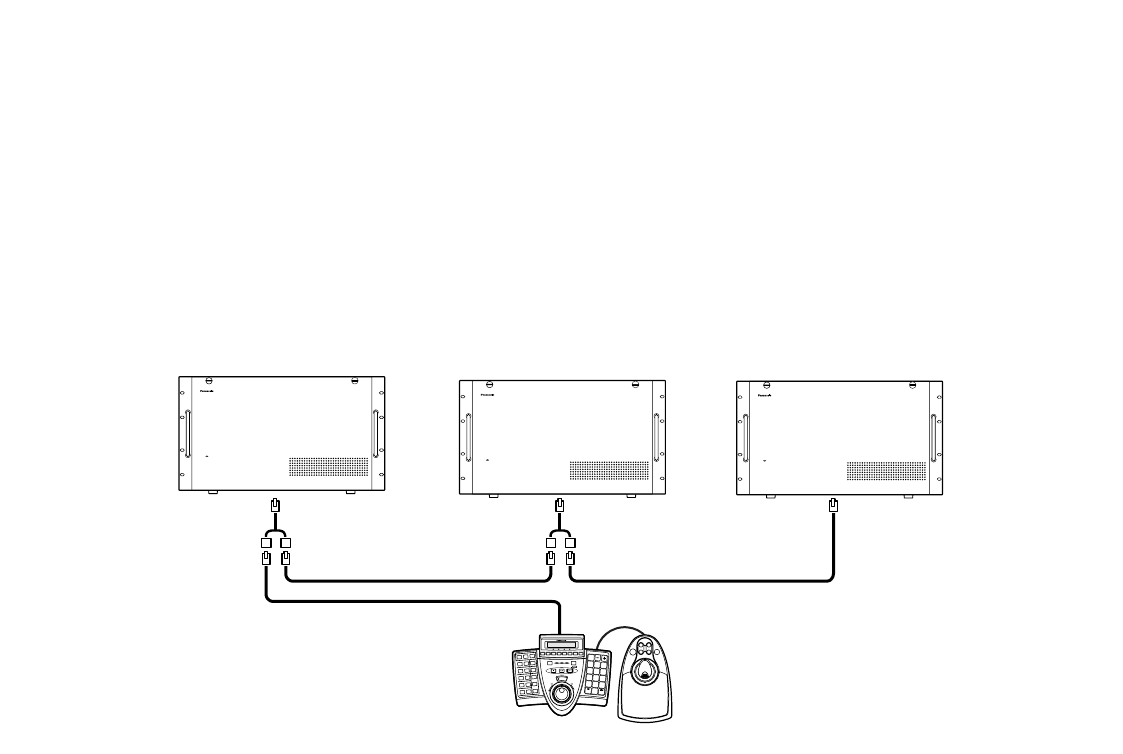
■ Connections of Matrix Switchers (WJ-SX650 Series) and a PS·Data
System Controller
By setting the DATA ports of matrix switchers to PSD in SETUP MENU (refer to p. 90) and connecting a PS·Data system con-
troller (CONTROLLER NO.: 1) to one of the ports, you can control these units from the system controller. (Refer to p. 69 for
details on connections.)
By connecting a PS·Data system controller (CONTROLLER NO.: 1) to the DATA ports of the units with Cable Kit WV-CA48/10K,
you can control these units from the system controller. (Refer to p. 69 for details on connections.)
Notes:
•Connect Cable Kit to the DATA 1 port.
• Set the DATA 1 port of each unit to PSD. (Refer to p. 90.)
Connections and Operations
•When controlling two or more units from a PS·Data system controller, you need to select a unit before operation. Refer to
WV-CU950/650 Operating Instructions for system unit selection.
• The unit address of each unit must be different from that of system controller. The unit address settings are performed in
"Communication" – "PS·Data" of WJ-SX650 Series Administrator Console.
•When an alarm occurs to a unit, other units will accept the alarm as a serial alarm input.
• User level settings for alarm suspension must be the same within all the units. If alarm suspension is restricted in the level
setting of a unit, operators with the restricted levels cannot suspend even alarms occurring to other units.
• The LCD settings are performed in "System" – "Logical Camera Number" of WJ-SX650 Series Administrator Console. Up to
LCN 999 are available for the settings.
■ Controlling from a Web Browser Accessing a Recorder
If a recorder is connected to the unit, you can control cameras using a web browser installed on a PC accessing the recorder.
You can set priority for web browser control. Priority setting is performed in "Operator" – "Operator" of WJ-SX650 Series
Administrator Console.
Notes:
• Refer to the operating instructions of recorder for details on browser control.
• Regardless of priority setting, during the recorder control from a system controller, camera control is not available from a
web browser accessing recorders connected to the same DATA port in the daisy chain.
■ Controlling from a PC
You can perform the operations and functions of system controllers by logging into the system and sending RS-232C com-
mands from a PC connected to the unit. Refer to Serial (RS-232C) Connector Command Reference (PDF file on the supplied
CD-ROM) for available commands.
Matrix Switcher WJ-SX 650
Matrix Switcher WJ-SX 650
Matrix Switcher WJ-SX 650
A B
1
3
2
4
6
5
7
9
8
0
SYSTEM CONTROLLER
OPERATE
OPERATE LED WILL BLINK
IF COOLING FAN MALFUNCTIONS
OPERATE
OPERATE LED WILL BLINK
IF COOLING FAN MALFUNCTIONS
Cable Kit
WV-CA48/10K
CONTROLLER NO.: 1
Unit Address: 1
Unit Address: 2
Unit Address: 3
OPERATE
OPERATE LED WILL BLINK
IF COOLING FAN MALFUNCTIONS


