


162
I/O UDP
I/O UDP
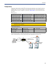
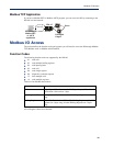
Industrial applications often monitor the status of I/O devices such as sensors, alarms, relays, etc. by
polling for I/O data. The IOLAN’s I/O UDP feature can help to minimize network traffic by
broadcasting I/O status to industrial applications on specified intervals, providing I/O status in a
timely manner.
The IOLAN’s I/O UDP broadcast feature sends the status of attached I/O devices to defined hosts on
the network. Depending upon the IOLAN model and the configuration of the I/O channels, the UDP
packet contains the current status and/or data of each enabled I/O channel or serial pin signal.
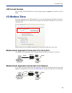
UDP Unicast Format
PC applications must be able to interpret the UDP packet to obtain I/O channel status and data. This
section provides the detailed structure of the UDP datagram and its data format.
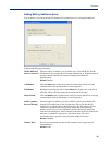
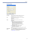
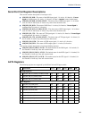
UDP Broadcast Packet
Ver si on
(1 Byte)
Total Packet Length
(2 Bytes)
Analog Section Digital/Relay Section Serial Pin Signal Section
Each section, with the exceptions of the Version and Total Packet Length sections, is comprised of its
own subset of bytes.
Note:
All 2 byte values are in big Endian (network) order. All 4 byte values are IEEE 754 single
precision floating point numbers in big Endian (network) order.
z Version—The current version of the format of I/O UDP broadcast packet.
z Total Packet Length—The total length of the UDP packet.
z Analog Section—The Analog Section of the UDP packet, which contains data/status of the
Analog I/O channels. The Analog Channel Data subsection (within the Analog Section) will only
exist if the channel(s) is enabled.
z Digital/Relay Section—The Digital/Relay Section of the UDP packet, which contains status of
Digital and Relay I/O channels. The Channel Data subsection within the Digital/Relay Section
will always be present.
z Serial Pin Signal Section—The Serial Pin Signal Section of the UDP packet, which contains the
status of the IOLAN’s serial port’s control signal pins. The Serial Pin Signal Data subsection
within the Serial Signal Pins Section will always be present.
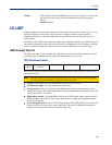
SNMP When enabled, sends an SNMP trap when an alarm is triggered or cleared. The
trap consists of the severity level and whether the alarm was triggered or
cleared.
Default: Disabled