


Setting Jumpers 215
Introduction
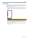
Digital I/O Module
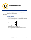
IOLANs that have Digital I/O have an input/output jumper that must be set for each channel and must
match the software configuration for each channel. Depending on the model, the placement of the
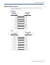
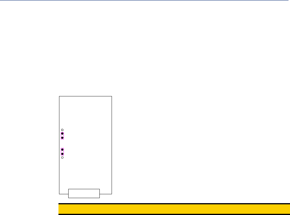
digital I/O board can change, so the diagram below shows how to set jumper for any digital board.To
change the settings, do the following:
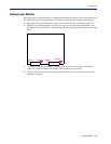
1. Detach the IOLAN from the electrical power source and disconnect everything from the box.
2. Open the case by unscrewing the five side screws, two on each side plus the grounding screw,
and lifting off the top of the case. You should see the following configuration for the digital I/O
board:
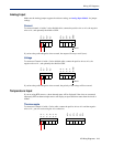
Pin1
J5
J3
Pin1
Channel 1/3
Channel 2/4
I/O
Note:
Jumper pins 1 and 2 for Input. Jumper pins 2 and 3 for Output.
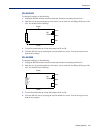
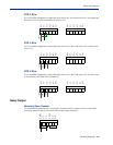
3. To configure either Channel 1 or Channel 3 (depending on how many Digital channels your I/O
supports and following the mylar channel definitions) for Input, jumper J3 pin 1 and 2 (as
shown); this is the default setting. To configure either Channel 2 or Channel 4 (depending on
how many Digital channels your I/O supports and following the mylar channel definitions) for
Output, jumper J5 pin 2 and 3 (as shown).
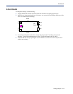
4. Close the IOLAN case by replacing the case lid and the five screws. You can now power it on
with the new settings.