


164
I/O UDP
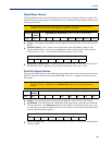
Digital/Relay Section
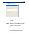
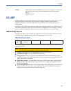
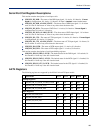
The Digital/Relay Section of the UDP packet provides the status of Digital and Relay channels. The
data for the status of each channel is represented by 1 byte, with each bit representing a channel (least
significant bit format).
Note:
The Digital/Relay Channel Data subsection is present in the UDP packet regardless of
whether or not the IOLAN model supports Digital/Relay channels.
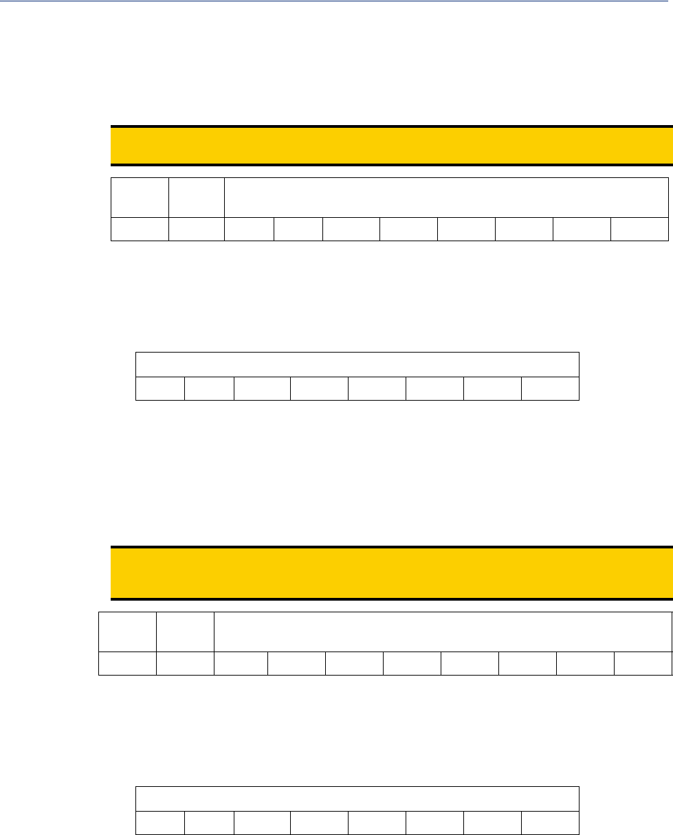
Length Channel
Enabled
Digital/Relay Channel Data (1 Byte, one bit for each channel)
z Length—The length of Digital/Relay Section within the UDP packet (this value will always be 2
Bytes).
z Channel Enabled—This is based on the configuration of the Digital/Relay channels. The
Channel Enabled field is 1 byte in least significant bit order, for each channel. If the channel is
enabled, the bit is set to 1. If the channel is disabled, the bit is set to 0 (zero).
Channel Enabled (1 Byte, one bit for each channel)
z Digital/Relay Channel Data—Each bit represents a channel status, 1 for on or 0 for off (unless
the channel has been configured to be inverted, in which case 0 is on and 1 if off).
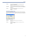
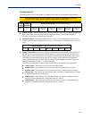
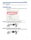
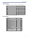
Serial Pin Signal Section
The Serial Pin Signal Section of the UDP packet provides the status of the serial pin signals from the
IOLAN’s serial port. Each serial pin signal (DSR, DTR, CTS, etc.) is mapped to a bit in the 1-byte
data section.
Note:
The Serial Pin Signal Data subsection is present in the UDP packet regardless of whether or
not the serial port is configured for the
Control I/O profile or the serial pin signals are
enabled.
Length Pin
Enabled
Serial Pin Signal Data (1 Byte, one bit for each signal)
z Length—The total length of the Serial Pin Signal Data (this value will always be 2 Bytes).
z Pin Enabled—This based upon the configuration of the signal pins on the serial port. When the
serial port profile is set to
Control I/O and a serial pin signal(s) is enabled, the bit is set to 1. For
any serial pin signals that are disabled, the bit is set to 0 (zero) and any data associated with those
serial pin signals should be ignored.
Pin Enabled (1 Byte, one bit for each serial pin signal)
z Serial Pin Signal Data—1 byte with each bit being set to high (1) or low (0) for the appropriate
serial pin signals.
2 Bytes 1 Byte Channel 4 Channel 3 Channel 2 Channel 1
Channel 4 Channel 3 Channel 2 Channel 1
2 Bytes 1 Byte RTS DTR CTS DCD DSR
RTS DTR CTS DCD DSR