


ThunderBird Avenger
TM
PCI Audio SAA7785
Accelerator
Philips Semiconductors Preliminary Specification
1999 Nov 12 13
timer data can be accessed as an I/O device. This timer can be used by game developers to keep track of time elapsed
to synchronize the video to the audio stream. The timer can be polled or interrupt driven and is selectable by the user
application.
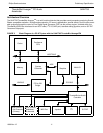
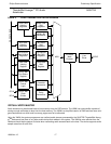
DMA
DMA is for the Sound Blaster registers, the DSP Mastering Device (DMD), and the S/P DIF output. To cover as many
systems as possible, the DMA interface supports three modes for legacy support: Mobile PC/PCI DMA Arbitration
(PC/PCI), Distributed DMA (DDMA) and Legacy Accommodation Mode (LAM).
Legacy Accommodation Mode allows the SAA7785 ThunderBird Avenger
TM
, in an architecturally compatible system, to
snoop and snarf selected DMA cycles on the PCI bus that were intended to the ISA Bridge. If a chip set supports Dis-
tributed DMA, the SAA7785 ThunderBird Avenger
TM
will use this method since it is more efficient than LAM. Addition-
ally, PC/PCI can be utilized as well if neither DDMA nor LAM are supported on the selected chip set.
AC Link
The SAA7785 ThunderBird Avenger
TM
chip provides support for the AC97 (V2.1) specification by supplying an AC Link
interface to communicate with industry standard AC97 CODECs. Up to two CODECs can be used for a total of 8 possi-
ble outputs (4 stereo channels).
Sound Blaster Registers
The other device that requires DMA is the SoundBlaster registers. DMA is used to transfer SoundBlaster digital audio
files from the host to a codec for playback in addition to providing a mailbox for other commands. In order for the DSP
to emulate the Sound Blaster sound effects, a legacy register set must be implemented to capture these commands.
These sixteen, 16-bit registers are used primarily to emulate SoundBlaster Pro register set as well as the SoundBlaster
Pro mixer registers. These registers are used as a mailbox to the DSP data bus to deliver data to the SoundBlaster
Emulation code. The SAA7785 ThunderBird Avenger
TM
chip supports DMA to the Sound Blaster that legacy code
requires. All data transmitted over the SoundBlaster Registers is processed by the DSP to emulate the Sound Blaster
Pro hardware.
OPL3 Registers and the FM Accelerators
The OPL3 register interface is a subset of the complete SoundBlaster register set. The OPL3 registers are separate to
point out that the FM legacy is supported at the register level. The OPL3 registers simply pass FM synthesis commands
to the SoundBlaster Emulation code and receive status from the same code.
Virtual Registers
The Virtual Registers interfaces the PCI bus and two substantial wavetable synthesis accelerators: the Sample Fetch
and Address Generation accelerators. The Virtual Registers is responsible for setting up the PCI interface for master
cycles data fetches and retrieving those fetches into a sample buffer. The Virtual Registers get commands from the
Address Generation accelerator and turns them into PCI master requests. Once the data has been retrieved, the Virtual
Register then instructs the Sample Fetch accelerator to process a block of data. Once the processing is complete, the
Sample Fetch Accelerator notifies the Virtual Registers that all is clear and that new data can be processed.
Address Generation Accelerator
The Address Generation accelerator is a preprocessing unit for the sample fetching mechanism inside the Virtual Reg-
isters. The Address Generator will get a set of parameters from the DSP code on a per voice basis for either Direct-
Sound processing or wavetable synthesis. Once these voice parameters are set, the hardware is instructed to translate