


ThunderBird Avenger
TM
PCI Audio SAA7785
Accelerator
Philips Semiconductors Preliminary Specification
1999 Nov 12 47
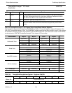
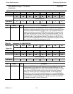
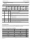
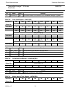
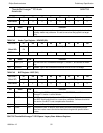
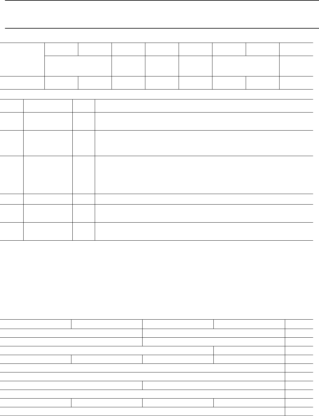
TABLE 32 Miscellaneous Configuration Register - MSCCFG (RO/RW)
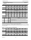
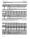
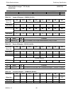
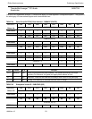
PCI Configuration Space 1
The following table is a summary of all the PCI configuration space registers. The registers that are block-mates with
the PCI interface (offset 00h - 3Ch) will be detailed following SSA7785 ThunderBird Avenger™. The remainder of the
registers will be detailed with the blocks they control. This register space is for the joystick.
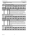
TABLE 33 PCI Configuration Space 1 Register Map
PCI CFG 0D7D6D5D4D3D2D1D0
Offset 58h
ASYMCLK[1:0] RDY_EN CFGCLK BHEN PCCH[1:0] PCPCI
_EN
POR Value
00000000
Bit Name R/W Function
7:6 ASYMCLK RW Asymmetrical Clock Select. These bits program the duty cycle for the input
for the two phase DSP clock generator.
5 RDY_EN RW Music registers ready enable. When set, the music registers will cause the
PCI interface to retry when either of the music registers (music0 or music1)
are full.
4 CFGCLK RW Serial Configuration Port Clock Select. This bit selects the clock output to the
Configuration Serial Port.
0 = Ouput a 400 KHz clock. Incoming data will be synchronized to this clock.
1 = Output the PCI clock.
3 BHEN RW Bus Hog Fix Enable.
2:1 PCCH RW These two bits are the encoded channel number that the soundblaster will be
on in the PC/PCI mode and are valid only when the PC/PCI mode is enabled.
0 PCPCI_EN RW PC/PCI mode enable bit. This bit, when set = 1, will enable the PC/PCI side-
band signals for the Soundblaster legacy mode.
Byte 3 Byte 2 Byte 1 Byte 0 Offset
Device ID Vendor ID 00h
Status Command 04h
Class Code Revision ID 08h
BIST Header Type Master Latency Timer Cache Line Size 0Ch
GMBASE 10h
Reserved 14-2B
Subsystem ID Subsystem Vendor ID 2Ch
Reserved 30-3Bh
Max_Lat Min_Gnt Interrupt Pin Interrupt Line 3Ch
Reserved 40-6Bh