


ThunderBird Avenger
TM
PCI Audio SAA7785
Accelerator
Philips Semiconductors Preliminary Specification
1999 Nov 12 30
PCI Master State Machine
This block will performs the handshaking between the PCI interface and the PM internal bus. The PCI master will per-
form bursting in a linear incrementing type fashion. The PCI master state machine may also wish to provide a target
lockout signal. This signal prevents the PCI target interface from responding to any master signals.
PC/PCI Legacy Support
The PCI block supports the PC/PCI sideband signals for legacy support of the soundblaster. The PC/PCI can be
enabled by a configuration register bit and one channel selected. The PCI slave block will provide the serial encoded
request signal (PCREQ#) in response to a request from the soundblaster and decode the serial encoded PCGNT# line.
The PCI slave will then claim I/O writes to address 0000h or 0004h with the PCGNT# line asserted as writes to the
SoundBlaster and pass the data to the SoundBlaster.
PCI Target State Machine
The PCI target state machine controls all SSA7785 ThunderBird Avenger™ target responses on the PCI bus in addition
to handling the PS internal bus.
PCI Target Control Logic
The target control logic handles the address decoding for the ps_NNNcs# signals, bus command decoding for the
ps_XXXrd# and ps_XXXwr# signals, determination of target abort conditions, and data path/pad control logic from the
target interface. Also included in this logic are the controls for the PCI datapath and I/O pads. These controls are sent to
the datapath logic where they are combined with the master controls and then sent to the datapath and pad devices.
The control logic also includes an interface to the PCI configuration headers.
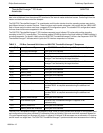
Serial Configuration Port
The Subsystem Vendor ID and Subsystem ID for each of the configuration headers presents a special case. These
three 32 bit registers must be programmed by the Subsystem Vendor. It is impractical to hard wire the Subsystem ID
registers since each Subsystem Vendor will have a unique ID. Therefore an external serial EEROM device is used to
download the proper values into the ID registers after reset and before begin read by the BIOS or other configuration
software. The PCI interface should force a retry if any of the subsystem registers have not completed a loading. The
Serial Configuration Port is a standard two pin I
2
C interface. The ThunderBird Q3DIII will supply the 400 KHz clock to
the external serial EEPROM on the CFGCLK pin. The serial data stream will arrive on the CFGDAT input pin. Please
refer to a 24LC00 128 bit I
2
C
Bus Serial EEPROM data sheet for interface protocols and timings.
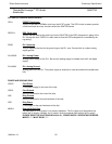
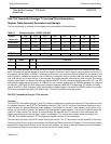
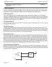
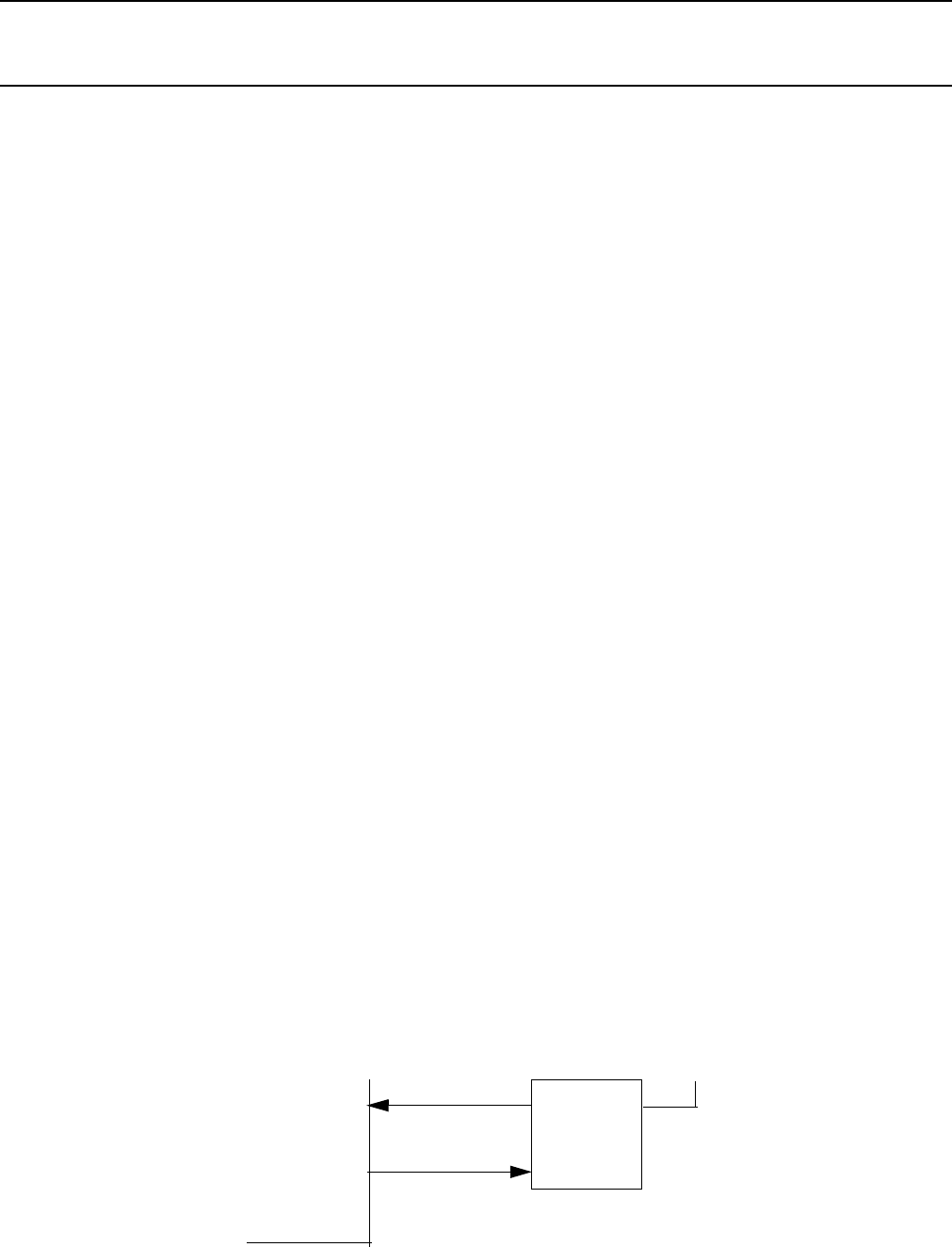
Serial Configuration Port Programming
The SSA7785 ThunderBird Avenger™ uses an inexpensive external EEPROM, programmed before installation, to
download the Subsystem Vendor ID and Subsystem ID registers for each function for a total of 96 bits (six 16 bit regis-
ters). The recommended device, a Microchip 24LC01B 1K Bit (128 Byte) Serial EEPROM, can be programmed using a
conventional DATA I/O programmer.
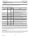
CFGDAT
ThunderBird
CFGCLK
+5V
SDA
WP
SCL
EEPROM