


ThunderBird Avenger
TM
PCI Audio SAA7785
Accelerator
Philips Semiconductors Preliminary Specification
1999 Nov 12 24
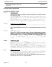
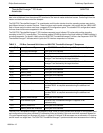
DSP SERIAL PORTS/GENERAL PURPOSE I/O
AC_RST_N# AC’97 Master Reset
The external AC’97 codec has a master reset line which is has a separate control. The codec
status must report a ready before any audio or modem data is transmitted to the codec.
SPDO Sony/Philips Digital Interface Format Output Port
Consumer format S/PDIF Output Port. The output characteristic of this pad approximates the
RS422 interface.
SPDI Sony/Philips Digital Interface Format Input Port
Reserved.
RWS Inter-IC Sound Bus Receive Port Word Select Clock/DSP General Purpose I/O 0
When the I
2
S is configured as a master, this pin will output a word clock at the frequency
selected by the user. When configured as a slave, the receive port will synchronize the left or
right channel data to this signal.
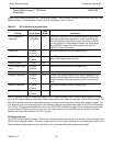
RSCK Inter-IC Sound Bus Receive Port Bit Clock/DSP General Purpose I/O 1
When the I
2
S is configured as a master, this pin will output a bit clock. When configured as a
slave, the receive port will shift in data from the RSD data stream using RSCK as an input.
RSD Inter-IC Sound Bus Receive Port Data/DSP General Purpose I/O 2
This pin is the input data stream for the I
2
S receive port.
TWS Inter-IC Sound Bus Transmit Port Word Select Clock
When the I
2
S is configured as a master, this pin will output a word clock at the frequency
selected by the user. When configured as a slave, the receive port will synchronize the left or
right channel data to this signal.
TSCK Inter-IC Sound Bus Transmit Port Bit Clock
When the I
2
S is configured as a master, this pin will output a bit clock. When configured as a
slave, the transmit port will shift out data from the TSD data stream using TSCK as an input.
TSD Inter-IC Sound Bus Transmit Port Data
This pin is the output data stream for the I
2
S transmit port.