


ThunderBird Avenger
TM
PCI Audio SAA7785
Accelerator
Philips Semiconductors Preliminary Specification
1999 Nov 12 14
the addresses and fetch the audio samples from system memory. The Address Generator is also capable of looping
without intervention from the DSP code. The DSP kills voices by instructing the Address Generator to stop fetching
data. Once the samples are fetched, they are stored in the Virtual Register’s input sample buffer for processing by the
Sample Fetch Accelerator.
Sample Fetch Accelerator
The Sample Fetch accelerator is used to process audio samples fetched by the Virtual Registers and deliver them to
the DSP code for further processing. This processing can include pitch shifting or sample rate conversion. The degree
of pitch shifting is under direction of DSP code indicating the Sample Fetch accelerator is programmable. The input
samples are taken from the Virtual Register’s input sample buffer and stored in DSP memory space.
MIDI Registers and UART
An MPU401 compatible UART is supplied to enable external MIDI devices to use the SAA7785 ThunderBird Avenger
TM
chip synthesizers as well as its external device’s own synthesizer. The MIDI register interface is used to pass the MIDI
command stream from the host to the DSP firmware for parsing into synthesizer commands. The MPU401 UART
always operates in “dumb” mode. Both the PCI and DSP can access the MIDI UART directly. Data is presented from/to
the MPU401 Registers in a mailbox fashion to the MPU401 UART.
General Purpose Input/Output
There are seven general purpose I/O pins that are controlled by the PCI bus (128 pin version). No GPIOs are available
in the 100 pin package.
PINE DSP Core
The Pine DSP core is a programmable 16-bit integer DSP with separate code and data busses (Harvard architecture).
Main features of the DSP core include 2K x 16 data RAM, 64K word code and data space, 16 x 16 bit two’s complement
parallel multiplier with 32-bit product, single cycle multiply/accumulate instructions, 36-bit ALU, two 36-bit accumulators,
six-general purpose 16-bit pointer registers, option for up to eight user-defined 16-bit registers, zero overhead looping,
repeat and block-repeat instructions with one nesting level, shifting capability, automatic saturation mode on overflow
while reading content of accumulators, divide and normalize step support.
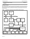
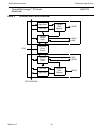
As noted on Figure 2, the DSP subsystem is supported by two dedicated Pine internal busses called the DSP code bus
and the DSP data bus. All DSP peripherals are connected to the DSP data bus while the code bus is used for just that,
DSP code ROM and RAM. Both the DSP code and data busses are 16-bit for the address and data lines on each bus.
DSP code also enables the DSP core to act as a PCI bus master making it a powerful and flexible audio processing
unit.
DSP Interrupt Controller
The DSP Interrupt Controller is a programmable, priority encoded device that encodes two interrupt signals to the Pine
core. The DSP Interrupt Controller resides on the DSP data bus and is programmed by DSP code. Both sets of inter-
rupt vectors feature an enable and status bit for each interrupt based device.
DSP Memory Controller
The DSP memory controller provides controls and decodes for the regular DSP data and code RAMs as well as the
code ROMs. The Memory Controller also includes a patch mechanism to allow ROM code to be updated or fixed using
a trapping device.