


ThunderBird Avenger
TM
PCI Audio SAA7785
Accelerator
Philips Semiconductors Preliminary Specification
1999 Nov 12 18
Game Port
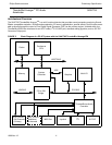
The SAA7785 ThunderBird Avenger
TM
Game Port interface is designed to emulate the PC-AT based legacy joystick
operation as well as support of a digital joystick mode. The legacy or analog, type of operation is designed to support all
legacy software that uses the original joystick address and the method for resolving the joystick axes positions. The
Digital Mode is designed to reduce the joystick overhead by resolving the joystick position directly and to support appli-
cations that use DirectInput.
The legacy joystick used a one shot multi-vibrator on each of the four joystick potentiometers. These one shots were
set up to deliver a pulse that was proportional to the resistor value of the joystick potentiometers. Software would them
poll the one shots to see if they had been set to the original value. The time it took for each axes to return to the original
value was resolved into a position by the legacy software. The SAA7785 ThunderBird Avenger
TM
emulates the 558
based one shot circuit to support legacy games that use the PC-AT joystick. The joystick button values were routed
directly to the system bus where only a decode was required to read the value of the button. Software would poll the
buttons as well. All button and joystick axes data is returned in a single byte wide register.
Game Port Legacy I/O Register
This register is the legacy mode register for the 558 based joystick. When in “analog” mode, this register is aliased to
respond to addresses at base + (0-7) . Reads from this register will poll the status of the joystick buttons and are used
to resolve the position. Writes to this register will discharge the external capacitors to emulate the 558 one shots. Soft-
ware can then poll the joystick register bit to resolve each of the joystick axes positions by timing. The joystick button
register bits have meaning in both the digital and analog modes. The axes bits are only valid for analog mode.
TABLE 3 Game Port 558-Based Register - GAMEPORT (RO)
I/O GMBASED7D6D5D4D3D2D1D0
Offset 1h JOYB_2 JOYB_1 JOYA_2 JOYA_1 JOYB_Y JOYB_X JOYA_Y JOYA_X
POR Value 11110000
Bit Name R/W Function
7 JOYB_2 RO Joystick B button 2 status. The joystick button status bits are cleared when
the respective joystick button is pressed.
6 JOYB_1 RO Joystick B button 1 status.
5 JOYA_2 RO Joystick A button 2 status.
4 JOYA_1 RO Joystick A button 1 status.
3 JOYB_Y RO Joystick B y-coordinate. Can also be referred to as position 3.
2 JOYB_X RO Joystick B x-coordinate. Can also be referred to as position 2.
1 JOYA_Y RO Joystick A y-coordinate. Can also be referred to as position 1.
0 JOYA_X RO Joystick A x-coordinate. Can also be referred to as position 0.