Interfaces7–2
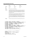
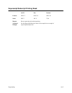
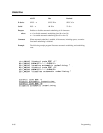
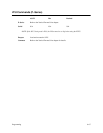
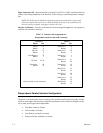
Paper Instruction (PI) – Optional standard or inverted level EVFU or DVFU signal from the host
with
the same timing and polarity as the data lines. PI line sensing is controlled by printer configura
-
tion.
NOTE:
The PI line must be disabled (configuration option selected fr
om the contr
ol panel)
if
the host
computer does not drive or contr
ol the PI line. If the line is not contr
olled by the
host
and sensing is enabled, rapid paper slewing will occur
.
Interface
V
erification
– T
wo pins on the interface connector jumpered together to
verify proper in
-
stallation of the interface connector.
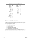
Table 7–1. Connector Pin Assignments for
Dataproducts Interface with AMP Connector
Signal Pin
Data Line 1
Data Line 2
Data Line 3
Data Line 4
Data Line 5
Data Line 6
Data Line 7
Data Line 8
Paper Instr.
Data Strobe
Return
Return
Return
Return
Return
Return
Return
Return
Return
Return
Ready
On Line
I/F Verif.
Return
Data Request
19
3
20
4
1
2
41
40
34
18
43
42
36
35
28
44
30
14
38
37
22
6
21
23
45, 46
Return 5
Return 7
OUTPUT INPUT
Pins not listed are not connected.
Signal Pin
Dataproducts Parallel Interface Configuration
The
printer is configured at the factory according to the specified interface. However
, printer configu
-
ration
can be changed. The following configuration parameters can be verified or
changed as neces
-
sary to meet specific application requirements:
• Data Bit 8 (enable or disable)
• PI line (enable or disable)
• Data Polarity (standard or inverted)
• Response Polarity (standard or inverted)


