4–9Graphics
DOUBLE DENSITY PLOT
For
double density plot, the plot line
contains: Control Code 04 hex, plot data bytes, a Line T
erminator
(0A
hex or 0C hex), Control Code 05 hex, plot data bytes,
and a Line T
erminator
. The control sequence
for
sending P–Series
Double Density Plot
is as follows:
1. Send
the even dot plot control code EOT (04 hex), followed by plot data bytes. (Refer to T
able
4–1
on page 4–1
1.)
2. Send
a line terminator
, which causes the printer to plot the data bytes. The paper is
not
advanced
in
Double
Density Plot; the printer now waits for the second plot command and plot data bytes.
3. Send
the odd dot plot control code ENQ (05 hex) and a second line of data, followed by a line
terminator.
a. A
line feed (0A hex) used as the line terminator plots the contents of the buf
fer and advances
the
paper a
single dot r
ow
, based on the vertical density of the current mode. A CR (if CR =
CR + LF is configured) may also be used with the same result.
b. A
form feed (0C hex) used as
the line terminator plots the data bytes and advances the paper
to the
top of the next form.
4. Regardless
of which line
terminator code is sent, the printer defaults to the previously selected
print mode unless further plot control codes are provided with the data.
NOTE: Failur
e to adher
e to this format may cause unexpected r
esults.
Plotting the Data
P–Series
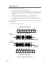
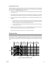
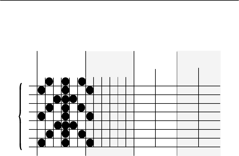
Plot Mode plots the image from the horizontal bit pattern. Figure 4–8
duplicates the pattern
shown
in Figure 4–4 but is modified for Odd Dot Plot. Eight dot rows are required, two characters per
row,
six columns per character
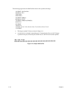
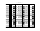
. (The dots required to produce the pattern are shown Figure 4–9 on page
4–10.)
1
2
3
4
5
6
7
8
13 11579 13 11579
1st
CHARACTER
ODD COLUMNS
2nd
CHARACTER
ODD COLUMNS
1st
CHARACTER
ASCII DECIMAL
2nd
CHARACTER
ASCII DECIMAL
42
73
92
42
73
92
42
73
*
|
\
*
|
\
*
|
64
65
64
64
65
64
64
65
@
A
@
@
A
@
@
A
DOT
ROW
Figur
e 4–8.
Odd Dot Plot Pattern Plan


