7–3Interfaces
• Strobe Polarity (standard or inverted)
• Latch Data On Leading or Trailing Edge of Strobe
These parameters are displayed under the Application Compatibility/Host Interface/Dataproducts
submenu
from the control panel. Refer to Control Panel Configuration Diagram in the Configuration
chapter for information on selecting the various parameter values.
Based
on
the application, a unique configuration may be required. If the printer is not working properly
for the configuration selected, contact your authorized service representative.
NOTE:
The PI line must be disabled fr
om the contr
ol panel if the host computer does not
drive
or contr
ol the PI line. If the line is not contr
olled by the host and sensing is enabled,
rapid
paper slewing will occur
.
Centronics Parallel Interface
This
interface enables
the printer to operate with controllers designed for buf
fered Centronics printers.
The
maximum data line length (cable length) from the controller (host computer) to the printer is 40
feet.
Centronics Interface Signals
T
able 7–2
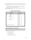
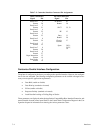
lists the Centronics interface connector pin assignments. Centronics interface signals be-
tween the computer and the printer are defined as follows.
PE – A high true level from the printer indicating the printer is in a check condition.
SLCT
– A high true level from the printer indicating the printer is ready for data transfer
and the ON
LINE
switch has been activated.
Busy
– A high true level from the printer indicating the printer cannot receive data.
ACKNLG
– A low true
pulse from the printer indicating the character or function code has been re
-
ceived and the printer is ready for the next data transfer.
Data Strobe – A low true, 100 ns min. pulse from the host to clock data into the printer.
Data
Lines
– Eight standard or inverted levels from the host that specify a character or function code.
Sensing Data Line 8 is controlled by printer configuration.
Paper
Instruction (PI)
– Optional EVFU or DVFU control signal from the host with the same
timing
as the data lines. Sensing the PI line is controlled by printer configuration.
NOTE:
The PI line must be disabled fr
om the contr
ol panel if the host computer does not
drive
or contr
ol the PI line. If the line is not contr
olled by the host and sensing is enabled,
rapid
paper slewing will occur
.


