Interfaces7–4
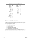
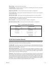
Table 7–2. Centronics Interface Connector Pin Assignments
INPUT
SIGNALS
OUTPUT
SIGNALS
Signal Pin Signal Pin
Data Line 1
Data Line 2
Data Line 3
Data Line 4
Data Line 5
Data Line 6
Data Line 7
Data Line 8
Data Strobe
Return
Return
Return
Return
Return
Return
Return
Return
Return
ACKNLG
SLCT
Busy
Chassis
Spare
Return
Return
PE
Ground
2
20
3
21
4
22
5
23
6
24
7
25
8
26
9
27
1
19
10
28
32, 13
12
11
29
17
30,31,
34,35,
36
Paper Instruction
Return
15
14
Centronics Parallel Interface Configuration
The
printer is configured at the factory according to the specified interface. However
, the configura
-
tion
is also user selectable. The following configuration parameters can be verified or changed as nec
-
essary to meet specific application requirements:
• Data Bit 8 (enable or disable)
• Data Polarity (standard or inverted)
• PI line (enable or disable)
• Response Polarity (standard or inverted)
• Latch Data On Leading or Trailing Edge of Strobe
These
parameters are displayed under the Application Compatibility/Host Interface/Centronics sub
-
menu
selectable from
the control panel. Refer to the Control Panel Configuration Diagram in the Con
-
figuration chapter for information on selecting the various parameter values.


