7–Removal and Replacement
Power and Cooling Modules
7-10 ISR651101-00 J
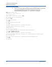
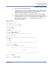
Password : ******
iSR6200 <1> (admin) #> fru restore
A list of attributes with formatting and current values will follow.
Enter a new value or simply press the ENTER key to accept the current value.
If you wish to terminate this process before reaching the end of the list
press 'q' or 'Q' and the ENTER key to do so.
Type of restore (0=full, 1=mappings only) [full]
0
FRU restore completed.
Please reboot the system for configuration to take affect.
iSR6200 <1> (admin) #>
reboot
Are you sure you want to reboot the System (y/n): y
System will now be rebooted...
iSR6200 #>
Connection to host lost.
The replacement blade should now be operational.
Power and Cooling Modules
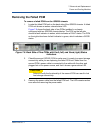
Each iSR6200 chassis blade has a PCM, located on the back side of the chassis.
Each PCM consists of one power supply, three fans, and one external status LED.
The PCM’s external status LED shows its status:
Green = GOOD status, indicating that the PCM is running as expected.
Amber = FAULT status, indicating that the PCM has failed.
You can remove and replace a failed PCM as described in the following sections:
“Removing the Failed PCM” on page 7-11
“Installing the Replacement PCM” on page 7-12


